Grand Prize Winner
(Dec 2012)
Second Prize Winner
(July 2012)
Donations Development in general requires time and money. Development of opensource projects is not an exception. To keep this online resource alive we heavily rely on your donations. If you feel like supporting us please make a donation.
DefendLineII has a native support of JPEG Colour Camera (C328 compatible). Such type of camera is capable of delivering VGA quality still pictures, it is equipped with hardware JPEG compressor and serial interface making integration with embedded devices quick and easy. This camera requires two wires (RX and TX) for serial communication, ground and positive power wires. Peak power consumption reaches 60mA at 3.3V but most of the time camera stays in stand-by mode making it quite attractive for security, monitoring, medical embedded applications and designing of robot-kits of any kind, this description perfectly fits to our needs. The camera looks like that:
 C328 Camera Potentially DefendLineII is capable of supporting for up to three serial cameras (in this case USB port won’t be available) but in this example we are going to demonstrate how to handle only one camera connection. Check carefully camera header pinouts before connect it to CONN3 serial header located on our board. Pin interconnection table is given below:
| Signal name |
Wire color |
C328 camera J1 header |
DefendLineII CONN3 header |
| Vcc (3.3V) |
Red |
1 |
6 |
| Camera Tx |
Yellow |
2 |
1 |
| Camera Rx |
Green |
3 |
3 |
| GND |
Black |
4 |
2,4 |
Software support is provided by a class implemented in SerialCamera.c file. The class exploits all camera’s features described in great detail in C328 User Manual. In order to take a picture five basic steps should be performed: synchronization procedure (series of specific byte sequence to wake up the camera), initial camera settings (JPEG or RAW mode, picture resolution), setting up of a package size (pictures are split into packages when being sent to the host controller), making a snapshot itself (issuing a command to read raw data from sensor and store it in internal camera RAM) and finally reading of a stored picture in a loop package by package until the whole picture is received.
On the very top level the interactions with a camera are encapsulated in DefendLineII.c in just two methods: uint8_t takePicture(char* fileName, uint16_t resCode) and volatile void onPicturePacketReceived(uint8_t* buf, uint16_t len, struct fat_file_struct* fd). The first one initiates camera and MicroSD filesystem, requests a snapshot and the second method handles data portion every time when next package arrives. When the operation is successfully completed a JPEG file will be stored in current directory on MicroSD card.
The process of taking pictures might be triggered manually in terminal. Insert MicroSD into its slot, connect the camera to CONN3 header, connect board to your PC via USB cable, power up the board and launch terminal application. Type test and the device should report that MicroSD and Serial camera are detected and initialized (please refer to DefendLineII. Terminal commands for more information). If this step was successful you can take a picture. Point your camera to a desirable object and type takephoto [filename]. Orange LED will start repeatedly blinking as indication of data transfer and in a few seconds a new captured image will be stored on a flash card in JPEG format.
Files stored on a flash might be transferred to PC in two ways – by sticking MicroSD directly into computer with help of a card reader or by means of cat [filename] command in terminal which outputs the content of binary files as dump of hex data. Later this dump could be converted into binary file so that the file will be viewable. In the nearest future it is planned to employ lightweight ZModem protocol to facilitate file transfers between the board and PC.
A great deal of DefendLineII configuring might be done over a terminal. To use this option the board must be connected to PC via USB cable and serial selector JP1 must have pins 1 and 2 connected together. As a terminal program standard Windows HyperTerminal can be used but it is not very convenient tool, we recommend to download Tera Term Open Source project. Again, set up your terminal to open the right virtual COM port with 115200 bps baud rate, 8 bit data, none for parity, 1 stop bit and none for flow control. All commands are case sensitive and must be ended with Enter. Parameters (if any) are entered after command and separated by spaces. List of available commands might be obtained by help command, the output is below:
help
=== DefendLineII V1.0, October, 2010 ===
=== visit https://magictale.com ===
Device name: DLII_SYD_01
Avail.commands: test, bootldr, ls, mkdir, cd, rm, df, cat, touch, sync, takephoto, write, set time, get sensor descr, set sensor descr, get device name, set device name
test command retrieves board’s configuration and tests some components and external devices. Typical command output is given below:
->test
AVR ATMEGA1280 CPU
Temperature sensor DS1621 – detected, current temperature: 33.0 degrees C
RealTime clock PCF8563 – detected, current time: 20:17:24 14/11/2010
MicroSD card – detected
SerialCamera – detected
SerialCamera initial – success
SerialCamera setPackageSize – success
SerialCamera snapshot – success
The information above means that main board CPU is ATMEGA1280, temperature sensor is installed and works, realtime clock chip is installed and works and both MicroSD card and JPEG serial camera are detected and successfully passed initialization.
bootldr command forcibly launches bootloader but please note that avrdude won’t have access to the serial port until terminal application is running, you will be given 5 seconds to close the terminal and run avrdude command. More convenient way is to press SB1 button and hold it until avrdude command is performed, of course in this case terminal application must be closed as well. The command output is given below:
->bootldr
Bootloader will be starting in 5 seconds…
ls command displays the content of current MicroSD card directory in format file(directory) name and file length. Typical output is given below:
->ls
2010/ 0
2009/ 0
2008/ 0
test01.jpg 9788
test02.txt 17
mkdir [dirname] command creates a new directory. First and the only parameter is directory name. Currently names with spaces are not supported, typical output is:
->mkdir 2007
success
cd [dirname] command changes current directory. To return to root directory cd .. command should be used. A typical command output is given below:
->cd 2010
success
->ls
./ 0
../ 0
test01.jpg 0
rm [name] command removes file or directory.First and the only parameter is file or directory name. Typical output:
->ls
2010/ 0
2009/ 0
2008/ 0
2007/ 0
->rm 2007
success
->ls
2010/ 0
2009/ 0
2008/ 0
df command retrieves system information about MicroSD card. Typical output:
->df
manuf: 0x3
oem: SD
prod: SU02G
rev: 80
serial: 0x4D7C004
date: 3/10
size: 1886MB
copy: 1
wr.pr.: 0/0
format: 0
free: 1973747712/1975287808
cat [filename] command displays file content. Text files will be displayed as text, all other types – as dump of bytes. Typical output:
->cat test11.jpg
0: FF D8 FF E0 0 11 4A 46
8: 49 46 0 1 2 3 4 5
10: 6 7 8 9 A FF DB 0
18: 43 0 10 C C E C A
20: 10 E E E 12 12 10 14
28: 18 28 1A 18 16 16 18 32
30: 24 26 1E 28 3A 34 3E 3C
38: 3A 34 38 38 40 48 5C 4E
40: 40 44 58 46 38 38 50 6E
…
touch [filename] command creates a new empty file with given name. Typical output:
->ls
./ 0
../ 0
->touch myfile.txt
success
->ls
./ 0
../ 0
myfile.txt 0
sync command performs MicroSD card synchronization. Useful if the card has been inserted/replaced without switching the board off. Typical output:
->sync
success
takephoto [filename] command takes photo and stores it in a file with given name. Note, that this command works only if a JPEG serial camera is connected to a COM port (currently COM1). More information will be provided in a separate article.
write [filename] command reads text lines from terminal and writes into previously created file. Currently does not append into the end of file, previous file content will be rewritten if exists. Typical output:
->touch test03.txt
success
->write test03.txt
opening file…
please type file content, double to finish file appending
line1
line2
line3
success
->cat test03.txt
line1
line2
line3
set time [HH:mm:ss DD/MM/YYYY] command sets RTC chip date and time, typical output is given below:
->set time 10:55:00 14/10/2010
success
get sensor descr [sensor_num] command retrieves user defined sensor description which simplifies event identifications. This data is stored in EEPROM memory segment and won’t be lost during power outages. Maximum name length is 16. Sensor_num parameter is in range 0..3. Typical output is given below:
->get sensor descr 1
curr. value: Main door
success
set sensor descr [sensor_num] [description] command stores user defined sensor description into EEPROM memory segment. Sensor_num is in range 0..3 and description is a textual sensor description.
get device name command retrieves user defined board name. This data is stored in EEPROM memory segment and won’t be lost during power outages. Maximum name length is 16. Typical output:
->get device name
Device name: DLII_SYD_01
success
set device name [device_name] command stores user defined board name into EEPROM memory segment. Device_name is a textual string.
Previous article: DefendLineII. Building firmware;
Additional info: DefendLineII Kit;
Building firmware is pretty much similar to building bootloader described in the previous article. Assuming that you have WinAVR and SVN already installed, your DefendLineII PCB has bootloader flashed and avrdude can communicate with the board so you are ready for the procedure.
Download source code for DefendLineII project if you have not done it yet by entering the following command line in Command Prompt:
svn co https://defendline2.svn.sourceforge.net/svnroot/defendline2 defendline2
The source files will be located in \defendline2\CPP\DLII_Main\ folder and make file will be in \build subdirectory. In Command Prompt change current directory to \defendline2\CPP\DLII_Main\build and type make without parameters, in case of success there will be the output similar to this:
 Compiling DefendLineII The file we are after is DefendLineII.hex, it will be located in /build directory along with many others generated by building procedure. Connect your board with USB cable to PC and type the following command (com4 should be replaced with com1…com3 depending on your virtual COM port configuration):
avrdude -p m1280 -c avrisp -P com4 -b 57600 -U flash:w:DefendLineII.hex
Immediately after issuing the command power up the board while holding SB1 button until the flashing process starts. While flashing green LED will be blinking fast as an indication of board-host data exchange. After flashing process red and blue LED will be blinking repeatedly, it means that the procedure was successfully completed and main program block is up and running.
Next step will be checking if your board communicates via terminal program. Standard Windows HyperTerminal can be used but it is not very convenient tool, we recommend to download Tera Term Open Source project. Set up your terminal to open the right virtual COM port with 115200 bps baud rate, 8 bit data, none for parity, 1 stop bit and none for flow control. Type ‘help’ in the terminal window and the board should respond with its name and list of possible commands:
 DefendLiniII Terminal Window Congratulations! Your board is ready for experiments. Next article will give a detail description of the board’s terminal commands.
Previous article: DefendLineII. Flashing bootloader;
Next article: DefendLineII. Terminal commands;
Additional info: DefendLineII Kit;
A bootloader is a compact executable code often flashed in upper program memory area implementing basic transfer protocol and facilitating self-programming function, making possible firmware updates without need to have an external programmer. In most cases bootloaders simulate basic programmers to take advantage of already existing software support without invention of something new. Of course, initially a bootloader must be flashed by means of an external programmer.
To begin with, DefendLineII PCB must have as minimum the following components soldered: U3, C30, C31, Y3 (CPU and clock source); CONN20 (ISP connector for serial programming), R33, R34, LED2, LED3 (LEDs to indicate device states); L1, C4, C5.
Next we need an ISP programmer, let’s take as an example USBtinyISP AVR ISP Atmel Programmer. It costs only US $15.50, supplied with two flat cables (for 10 and 6 pin connectors) and is capable of providing a flashing board with +5V that is why there is no even need to solder power supply components at this stage. Download USB drivers required for the programmer, they are available here. Connect the programmer to a PC over a USB cable, Windows should report about newly found device and will ask for drivers. Unzip and install just downloaded archive. Now in Device Manager a new device called USBtinyISP AVR Programmer should appear in LibUSB-Win32 Devices group. The ISP programmer is ready for work, see the screenshot below:
 USBTiny ISP AVR programmer connected Now we need WinAVR, open source software development tools for the Atmel AVR microprocessors. The project contains many tools and utilities, development libraries, plenty of examples, tons of documentation and, of course, source codes but right now we will be using avr-gcc (C/C++ compiler) and avrdude (software support for huge diversity of AVR ISP programmers). Download the latest version and install the project. Open Command Prompt and type ‘avrdude’. If everything has been done correctly, a list of avrdude options will be displayed:
 Avrdude Options Now it is time to test whether the programmer can communicate with PC and the board. Connect the board and the programmer with 10-wire flat cable but before make sure that programmer’s ‘PWR’ jumper is closed – in this case the board won’t need a power supply (at least for now):
 DefendLineII flashing bootloader Type in Command Prompt the following command:
avrdude -p m1280 -c usbtiny -U hfuse:r:high.txt:h -U lfuse:r:low.txt:h -U efuse:r:ext.txt:h
If the board is functional the programmer will read high, low and extended values of fuse bites and write them in high.txt, low.txt and ext.txt files accordingly. Check the values of fuse bits carefully. In order to support external crystal and bootloader the following values must be written to the chip: 0x98 for high fuse byte, 0xD7 for low and 0xFF for extended one. If you have different values they can be changed with the following commands:
avrdude -p m1280 -c usbtiny -U hfuse:w:0x98:m
avrdude -p m1280 -c usbtiny -U lfuse:w:0xD7:m
avrdude -p m1280 -c usbtiny -U efuse:w:0xFF:m
Download source code for DefendLineII project. It might be done in two ways. If you have SVN tool installed then the following line in Command Prompt will create project’s folders along with all project’s files:
svn co https://defendline2.svn.sourceforge.net/svnroot/defendline2 defendline2
The target files will be located in \defendline2\CPP\BootLoader\ folder.
In case if you don’t have SVN installed you can simply download the files by browsing DefendLineII Bootloader in SVN repository. An already compiled file for flashing called ATmegaBOOT_168_atmega1280.hex could be fed to ISP programmer directly but in case if you want to compile it yourself you will need ATmegaBOOT_168.c and Makefile. Change the current directory to the one where these files are located and type the following command:
make mega
In case of success you should see something like this:
 Bootloader compilation process A just compiled ATmegaBOOT_168_atmega1280.hex will be located in the same directory. Now it could be flashed to the board, type the following line in Command Prompt:
avrdude -p m1280 -c usbtiny -U flash:w:ATmegaBOOT_168_atmega1280.hex
This procedure takes a few minutes because avrdude will flash almost all program memory despite that fact that the bootloader occupies only upper 4 kBytes. When the flashing is completed a control will be given to bootloader section first, the bootloader will start and attempt to read a command from PC host. Before that an onboard orange LED will blink, it is a good indication that everything is just fine.
Next step is to solder USB and power supply related components: U4, LED1, JP1, R3, R5…R10, C1, C2, C3, C6, C7, CONN1, Y1 (USB port hardware support); SB1 (for forcing device to start bootloader when flashed); CONN9, L3, L4, D4, D5, C32-C35, U7, R25, R26 (main power supply). When it is done, power up the board over CONN9 connector, there should be about +12V. Check the voltage after U7 DC-DC converter, it should be about +3.3V.
Disconnect USBtiny AVR programmer and connect the board to PC via USB, Windows should report about newly found virtual COM port and will install the drivers automatically. Now in Device Manager a new device called USB Serial Port should appear in Ports(COM&LPT) group, see the screenshot below:
 DefendLineII virtual serial port As avrdude has a limitation in serial ports range (from COM1 to COM4 only), we need to allocate the virtual serial port to COM3 or COM4 (COM1-COM2 are usually taken). Don’t forget to set port speed to 57600 in port’s settings.
Now you are able to update board firmware without any external ISP programmer, for instance, to flash DefendLineII.hex you need to issue the following command:
avrdude -p m1280 -c avrisp -P com4 -b 57600 -U flash:w:DefendLineII.hex
Note, that this time we use ‘avrisp’ programmer type and explicitly defining COM port and baud rate. There is also a trick: at first the abovementioned command should be issued then the DefendLineII board should be reset or powered up because the bootloader waits for some short period of time for a command from PC host and then it gives a control to the main program located at 0x0000 address in program memory. Another way to initiate flashing process is to hold SB1 button while the board is being powered up and until the flashing process starts.
Previous article: DefendLineII. Soldering tips;
Next article: DefendLineII. Building Firmware;
Additional info: DefendLineII Kit;
DefendLineII PCB will be distributed in three kits: just a PCB, without any components, a pre-assembled PCB with just ATMega1280, FT232BL, DS1621, PCF8563, MicroSD connector, crystals, ISP10 header and a few resistors/capacitors soldered and fully assembled with all components soldered. If you decided to solder component by yourself then we hope you will find these recommendations useful. The most challenging task is to solder 100-pin ATMega1280 with pin pitch = 0.4 mm. You must be heard many times that it is impossible to solder such chips manually? In reality it is not as scary as it looks – you just need to have certain set of ordinary tools, good soldering skills and patience. First of all, you will need a Clamp tool with magnifier. If could be found in many online stores, we ordered it in Farnell. That is how the magnifier looks like:
 Clamp tool with magnifier Secondly, you will need not just a soldering iron but a soldering station. It does not have to be an expensive one – something like Duratech TS1560 will be just enough, here is how the station looks:
 Duratech TS1560 Soldering Station And finally, you will need solder paste in syringe packaging, an invaluable ingredient for soldering/rework processes. We put
SMD291NL to a test, the item was purchased in Digikey and got quite satisfying results. The package filled with soldering paste looks like that:
 SMD291SNL soldering paste Now we are ready to solder the chip. Set up the soldering iron temperature to about 350 degrees Celsius (~660 degrees Fahrenheit), place the PCB of a desk in front of you. Make sure that the PCB is laying horizontally and you have enough light, (sunlight is preferable but not mandatory). Using the syringe apply soldering paste generously to cover all pads. Remove the chip from its packaging and carefully place it on the board aligning its pins along the pads. Pay a special attention to the chip’s orientation – it may look differently under the light from different directions – make sure that you pinpointed first pin correctly. Look at the chip through a magnifier – it will reveal possible problematic areas which would left unnoticed otherwise. Finally, all pins should be within pad areas without any overlapping. Solder one outer pin of any of four pin rows while gently holding the chip – either with help of fingers or tweezers. Check the results through the magnifier again. Correct chip alignment if it is necessary and solder another outer pin located diagonally from the first one. Check the results again. Solder the rest of pins. Keep in mind that you do not have to see a pin on a pad with great details – when a pin is soldered, the shape of pad is not flat anymore and it begins to reflect sunlight differently, so it is clearly visible which pins have been soldered and which have been not done yet.
When the process is completed you should have something like this:
 DefendLineII Under Magnifier Previous article: DefendLineII. Circuit Diagram;
Next article: DefendLineII. Flashing bootloader;
Additional info: DefendLineII Kit;
The heart of the unit is CPU ATMega1280 microprocessor running at 14.7456 MHz (Y3 crystal). This frequency provides required accuracy to clock serial communications at 57600/115200 bps between the unit and external devices such as PC, GPS module, GPRS modem, JPEG cameras etc. The ATMega1280 processor has four hardware serial ports facilitating simultaneous interactions with a few serial-aware modules. CONN19 is a standard JTAG header, CONN20 is a standard ISP10 header, its pinouts is fully compatible with very popular among hobbists USBTiny ISP AVR programmer. U8 and R32 components guarantee the RES (reset) active level when the power supply is not within working voltage range.
USB interface is implemented on a dedicated FT232BL chip (U4) and optional serial EEPROM AT93C46 (U1). There are many solutions allowing to work with USB without a dedicated chip but they all have a few significant drawbacks: main CPU must be clocked by either 6 or 12 MHz crystals (which is unacceptable in our case), more CPU resources are required to handle software USB interface, there is a need in USB drivers and these drivers do not usually exist for three major operating systems (Windows, Linux and MacOS) and finally, there are a few implementations of USB functionality in C/C++ languages but you have to pay for a right to use them in your own code. In contrary, FT232BL has rich software support – there are drivers for Windows, Linux and MacOS and in most cases they can be found automatically by operating system. The chip does all low level work and communicates with CPU via serial interface, also there is no need in copyrighted USB libraries on microcontroller side. FT232BL has its own 6 MHz crystal (Y1) so USB timings are not dependable on CPU clock. U1, R1 and R2 componets are optional and may not be soldered if there is no need to customize USB VID, PID, Serial Number, Product Description Strings and Power Descriptor. For interfacing with CPU only TXD, RXD and CTS signals are used, the rest (DTR, DSR, DCD and RI) are left unconnected. LED1 serves as visual indication of incoming/outgoing USB traffic. R35, R36 are for USB voltage detection so the moment when the voltage appears may be classified as a connection to PC. When USB connection is not used, U4 could be disconnected from CPU by means of JP1 jumper so the serial interface might be spared for a different application.
Temperature sensor and thermostat is implemented on DS1621 chip (U2). Temperature settings and temperature readings are all communicated to/from U2 over a simple 2-wire I2C serial interface. THRM line works as external interrupt waking up CPU when the measured temperature is outside of predefined range.
Real time clock/calendar PCF8563 (U5) has a dedicated 32768 KHz crystal (Y2). The clock chip has ALRM line triggering when alarm or timer goes off so that most of the time the CPU can stay in power down mode significantly reducing power consumption. Like temperature sensor, PCF8563 communicates with CPU over I2C serial interface.
Q2, R20, R18, D2 and CONN23 are designated to generate sound/voice through PWM driven SND line. If the feature is not vital, these components may be not soldered.
CONN2 is used for MicroSD card plugging. Hardware ports Serial0… Serial2 are available through CONN16, CONN2, CONN4 connectors. Serial3 port is designed to be an integration point with external transport modules such as GSM modem/Ethernet card/etc, the port is available through CONN17 header and along with traditional RX3, TX3 signals has RTS3, CTS3, STAT, PWRK, AIN extra lines and unregulated 12V power lines in case if an external module has its own power stabilizer with different voltage.
CONN14, CONN15, CONN21, CONN22 have PWM driven outputs so they can be used with some models of servo motors. CONN5 is I2C bus for external I2C (TWI) aware components or modules to be connected. CONN6 could be used as software driven 1Wire interface designed by Dallas Semiconductor.
User interface consists of two S1 and S2 buttons, optional LCD display with conventional contrast regulation and PWM driven backlight (R4 and Q3 components), LED1, LED2 are just for internal states or event indication, especially if LCD display is not installed, the LEDs might be programmed at designer’s discretion. Buttons’ behavior is also customizable.
CONN12 and CONN18 serve as extensions, their application is entirely up to designers. CONN has 6 general purpose IO lines, CONN18 has 10 GPIOs. In addition, CONN18 pinouts has been made compatible with LED Matrix Display project.
CONN1 is intended for connection for up to four external sensors if the module is used as alarm/security system, the header has a separate line for tampering detection and unregulated 12V output for powering active devices such as PIR sensors. R27, R29, R30, R31 and D6, D7, D8, D9, D10 protect CPU inputs from damaging from overvoltage.
Optional REL1, REL2, D2, D11, Q4 and Q5 elements are used for an independent commutation of two external AC driven appliances such as desk lamps, aquarium pumps or similar over two CONN10 and CONN13 connectors with normally connected and normally disconnected contact pairs.
The unit has dual power supply, main and backup, both of them use DC-DC regulators. Main power supply requires unregulated 12V on its input and it is built on U7, D4, C32, C33, D5, L4, R26, R25, C34 and C35 components. The backup one is functional with input voltage range from 0.8V to 14V, it consists of U6, C13, R7, L2, C14, D1, R19 and R22 components. Q1, R21, R23 and R24 are used for backup DC-DC converter automatic shutdown when there is main power supply. C8, R11, R12, C11, R13, R14 are used for main and backup power supply voltage monitoring.
The project’s circuit diagram is given below:
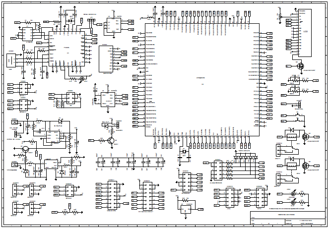 DefendLineII Schematics Previous article: DefendLineII. Overview;
Next article: DefendLineII. Soldering tips;
Additional info: DefendLineII Kit;
Note: Circuit diagrams are licensed under a Creative Commons Attribution Share-Alike license, which allows for both personal and commercial derivative works, as long as they credit ‘AVR Magictale Projects’ and release their designs under the same license.
Here is a demonstration of LED Matrix Display project working together with DefendLine. It is worth noticing that a digital video camera makes the display visibly flickering due to slightly different LED display and camera sensor refresh rates.
This article begins detail description of DefendLineII project and aims to simplify its assembling, setting up and further development by wide range of embedded controller designers and enthusiasts. First of all, traditional question, what is the purpose of designing a new hardware platform when there are a lot of things to choose from like Arduino, for instance? Well, to begin with, Arduino boards are designed as set of generic solutions for literally everything and most of the readers would probably agree that a generic way is definitely not the best one. To say more, the main page of Arduino site describes the product as ‘electronics prototyping platform… intended for artists, designers, hobbysts, and anyone interested in creating interactive objects or environments’, in other words, Arduino offers platform for rapid prototyping by virtually anyone, either with or without electronics and programming background.
In contrary, DefendLineII has pretty much definitive application field – objects control and automation in remote areas and which, in its own turn, automatically imposes certain requirements such as fault tolerance and reliability. Ability to work in remote and desolated areas means that the system must be fully functional in wide temperature range, must perform regardless of power instability or even outages, must be as power efficient as it is possible, must have embedded set of diagnostic tools for automated self checks and means to warn server side of when and what goes wrong, must have a feature to recover in case of unexpected external or internal events and must keep the ability to perform its primary task which in most cases is collecting, processing and sending data provided by sensors of any kind. DefendLineII was designed with these features in mind.
Secondly, Arduino boards allow connections with different extension boards called shields and this makes possible to get a desirable configuration capable of doing something specific. But again, designed to be generic, Arduino boards along with installed shields represent rather bulky assembly and the total cost of it is relatively high. In comparison, the main unit of DefendLineII was designed to be as compact as possible yet ergonomic enough and featuring SMD components soldered on both sides. Hardware facilities allowing the main unit interacting in a unified way with the outer world were deliberately separated from main board to have possibility to interchange transport layers so in order to make the system Ethernet/GSM/ZigBee compatible an appropriate transport module should be connected reducing overall costs and dimensions. In addition, some components which are not required for some particular solutions could be not soldered which is an extra point to minimize system’s cost.
As Arduino boards are intended for anyone it forced the designers to simply many things to make them easier to understand or use. It automatically creates some limitations hardly noticeable in case of generic basic projects. Indeed, DefendLineII is designed for people who have good soldering skills, some experience in embedded programming, not just programming and for people who are not afraid to spend a little bit more effort than in case of Arduino based projects to achieve outstanding results. And we are here to help you in this endeavor.
Next article: DefendLineII. Circuit Diagram;
Thank you for your attention and all the best,
Magictale team
 DefendLineII main unit PCB DefendLineII is the most advanced and multifunctional project of Magictale company so far. It was designed to be the second generation of DefendLine GSM alarm system allowing to break mobile phone dependency, aimed to minimise power consumption, increase overall system’s fault tolerance and remain fully functional in environments with harsh conditions like subzero and negative temperatures.
The documentation is available at DefendLineII preliminary User Guide
Main unit features:
- Includes Atmel ATmega1280 chip with 128k internal flash program memory clocked by 14.7456 MHz crystal;
- Power supply: 3.3 Vdc, dual independent stabilized power sources (7-14 V unregulated input as main source, 0.8-14 V input as backup or battery source), interrupt driven power failure detection ;
- Four independent input lines for alarm sensors (PIR sensors, etc) and one line for tamper detection;
- Two 10A 240 VAC relay outputs;
- Four hardware serial interfaces for communication with GSM/Ethernet/Bluethooth/Zigbee/GPS modules, JPEG CMOS cameras etc. (One serial port is used by onboard USB-to-Serial FT232BL chip to simplify device configuration, flashing and debugging procedures but USB functionality may be disabled by a jumper so there will be four serial ports at your service);
- Dedicated I2C real time clock chip;
- Dedicated I2C thermometer/thermostat chip;
- Standard AVR ISP 10-pin connector for in-circuit flashing;
- Standard JTAG 10-pin connector for in-circuit debugging;
- USB connection via serial port emulation, Win/Linux driver support;
- MicroSD slot for storing pictures, sounds etc;
- I2C connector for interfacing with tilt/accelerometer/motion etc sensors;
- Interface for 2×16 3.3V LCD display, backlight fading out feature;
- Two buttons for toggling modes;
- Three LEDs (green, red and blue) to indicate states, the first one is used for USB traffic indication, the last two could be programmed at designer discretion;
- Two extension connectors with 10 and 6 I/O lines;
- PWM driven interface to external speaker;
- Four interfaces to external servo motors;
- Pre-flashed bootloader allows to program the unit via USB, no need in external AVR ISP programmer;
- Open source firmware unlocks literally unlimited potential of this unit;
 DefendLineII V1.0 main unit assembled Currently the first main unit is underwent its testing phase including schematic solutions validation and PCB functional tests. First version of firmware is at intensive development stage and very soon will become available to the community as open source project at SourgeForge.net. PCBs will became available for buying fully assembled, not assembled (just bare PCB) and with some critical components soldered to simplify assembling for less advanced hobbists and beginners.
Next in a queue is a GSM module to give the system an access to the Internet while being installed at remote places.
Please express your interest by posting your comments.
It has been a while since a ‘magic pill’ for Sony Playstation 3 has been discovered causing the well-known console manufacturing giant suffering from huge financial losses, sending shockwaves across the Net, knocking down high-performance servers, stimulating abnormal demand for USB development boards and USB AVR processors in particular. All of a sudden thousands of people became hardware and firmware designers just overnight offering basically anything that could be potentially sold to PS3 owners for absolutely inadequate prices. Why is it so? The answer is simple – human greediness and ignorance, unwillingness to think rationally.
Let’s go through all key moments of this topic. First of all, there is a game console that is sold cheaper that the total cost of its design, components, assembly, testing and so on. Sony does it deliberately hoping to cover its expenses later and get some profit by selling games. Attempts to exploit the console to get an unlimited free access to all games that supposed to be bought means that less really good games will be produced just because developers (especially good ones) will be underpaid and eventually will face the prospect of leaving the company. Apart from this, the act of jailbreaking as such is against low, in other words, it is illegal. Everybody knows that, few consider it as a problem.
Even assuming that many gamers do not feel any remorse buying ‘the magic key’ it is still unclear why they are ready to pay the amount a few times more than real market price of the device. Indeed, that is really strange because the major driving force of the jailbreak was actually a desire to save hard-earned money, not waste. But what is happening it reality? Let’s follow the chain of events in chronological order. In peaceful times widely-recognised Teensy++ 2.0 board was about $30 USD. After referring by Resellers starting sell Teensy acticle the board price jumped to $39.89 USD. Already surprised? It is just a beginning. A lot of questionable hardware begins to appear, there is only one example: PS3Key. The ‘author’ wants to get $49 USD for it but look at the PCB soldering quality! Apparently, he was in such a hurry that did not have time to wash the flux away. Still it is not that bad if looking at the ebay item PSGroove-clone-Teensy-AT90USBKEY which was sold for $99 USD.
Simple calculations allow to estimate the real product value. Look carefully at Teensy schematics The most expensive components would be PCB itself and the USB AVR chip. Taking into account PCB dimensions and its complexity it should be sold at about $10 (try to compare with kits at Adafruit resource). As for the chip, AT90USB162 is priced for $3.71 USD, ATMEGA32U4 – for $6.04, AT90USB1286-AU – for $10.61 at Digikey, and it is retail, not bulk price, which means that the device’s real market price should be about $25 – $30 USD. As you can see, there is no point to rush and buy something that is quoted as much as $99 USD just because it is hot and popular at this very moment.
The bottom line of all this is really simple. It is much easier to hack something than build something. The application of AVR micro processors is much more broader, more interesting and more entertaining than just cloning USB PS3 keys. Be creative. Be inventive. And let the Power be with you.
Magictale Team
|