I sell on Tindie
Map
Grand Prize Winner
(Dec 2012)
Second Prize Winner
(July 2012)


Hacking Vodafone K4606 3G HSDPA USB Modem

The prospect of having high speed communication channel between an embedded project and outer world is very tempting. The challenge can be addressed by using a WiFi module in those areas with WiFi coverage being available but what if it is not an option? Then there is no other choice but GSM (also referred as 2G) module which substantially elevates the cost of overall solution and yet it is incapable of providing communication speed high enough for many nowdays needs. For example, prices for GSM Arduino shields currently available at Australian Little Bird Electronics are ranging between $71 and $118! The actual numbers for data exchange rate, however, are not that high and typically are in the vicinity of 9.6 Kbps for 2G networks. On the other hand, there are mobile broadband options like Vodafone USB Extreme 3G+ which can deliver data at up to 42 Mbps (download) and up to 5.76 Mbps (upload). Add to this virtually symbolic price tag for modem – Vodafone 3G+ USB stick would cost you $9(!) and it starts sounding like a fairy tale. The table below represents dramatic difference between the two solutions:

Modem type Communication speed Price, AU$
GSM Arduino Shield 9.6Kbps 71-118
Vodafone K4606 3G HSDPA USB Modem 42Mbps/5.76Mbps 9

Impressed by the inequality we were wondering whether it would be possible to use one of those USB broadband modems for embedded projects and eventually decided to pick Vodafone 3G+ modem to give it a try.
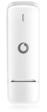
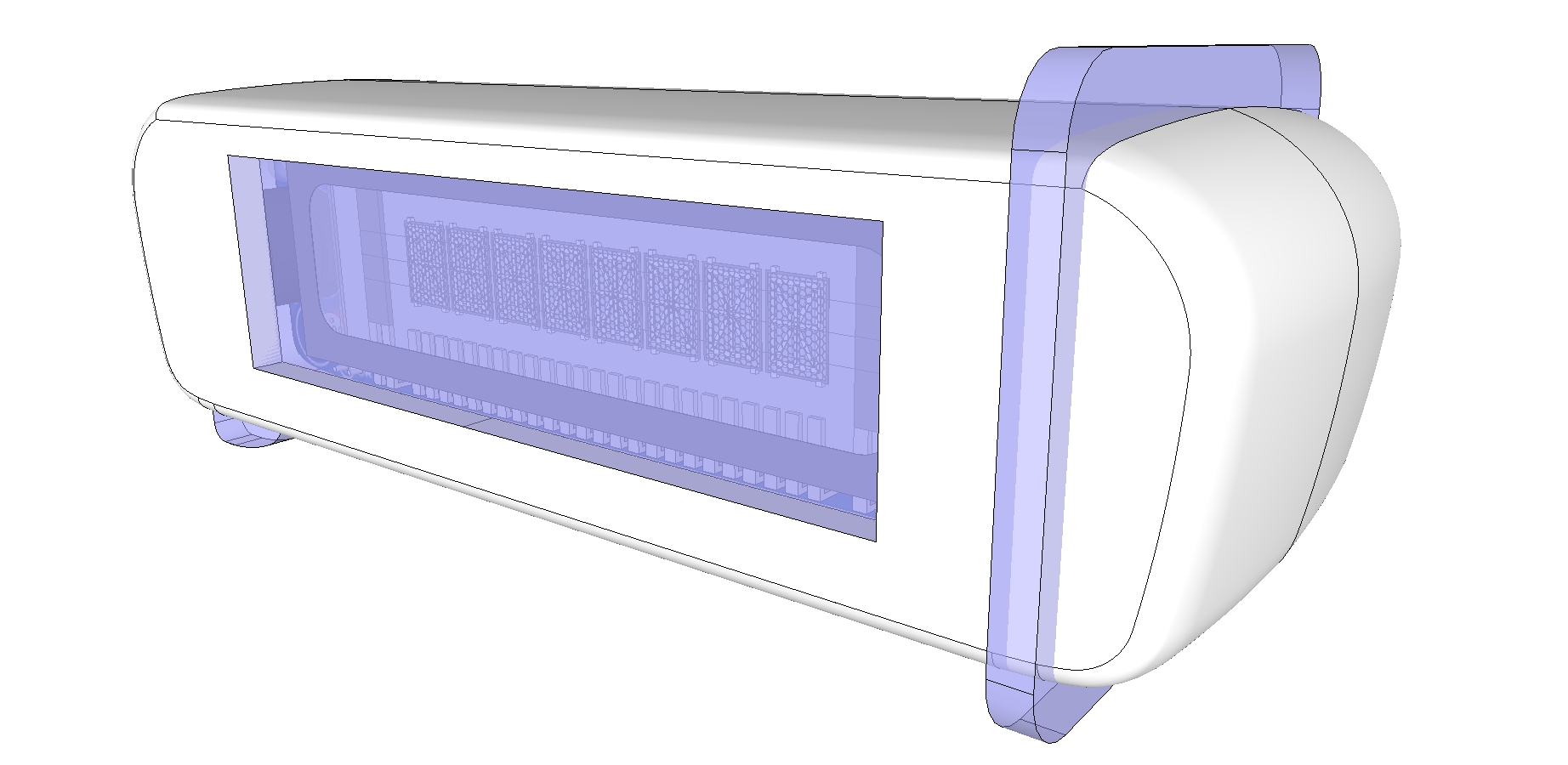
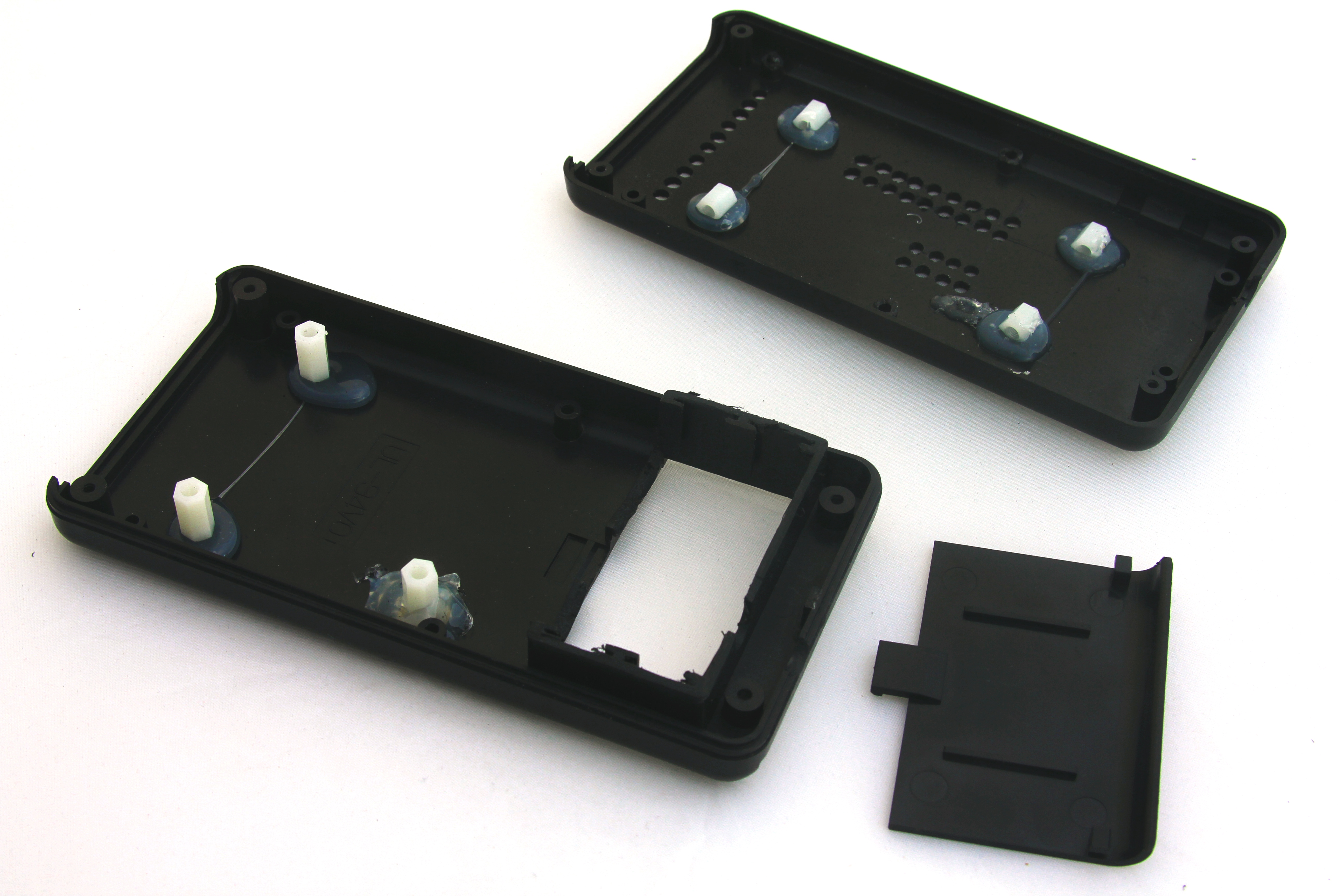
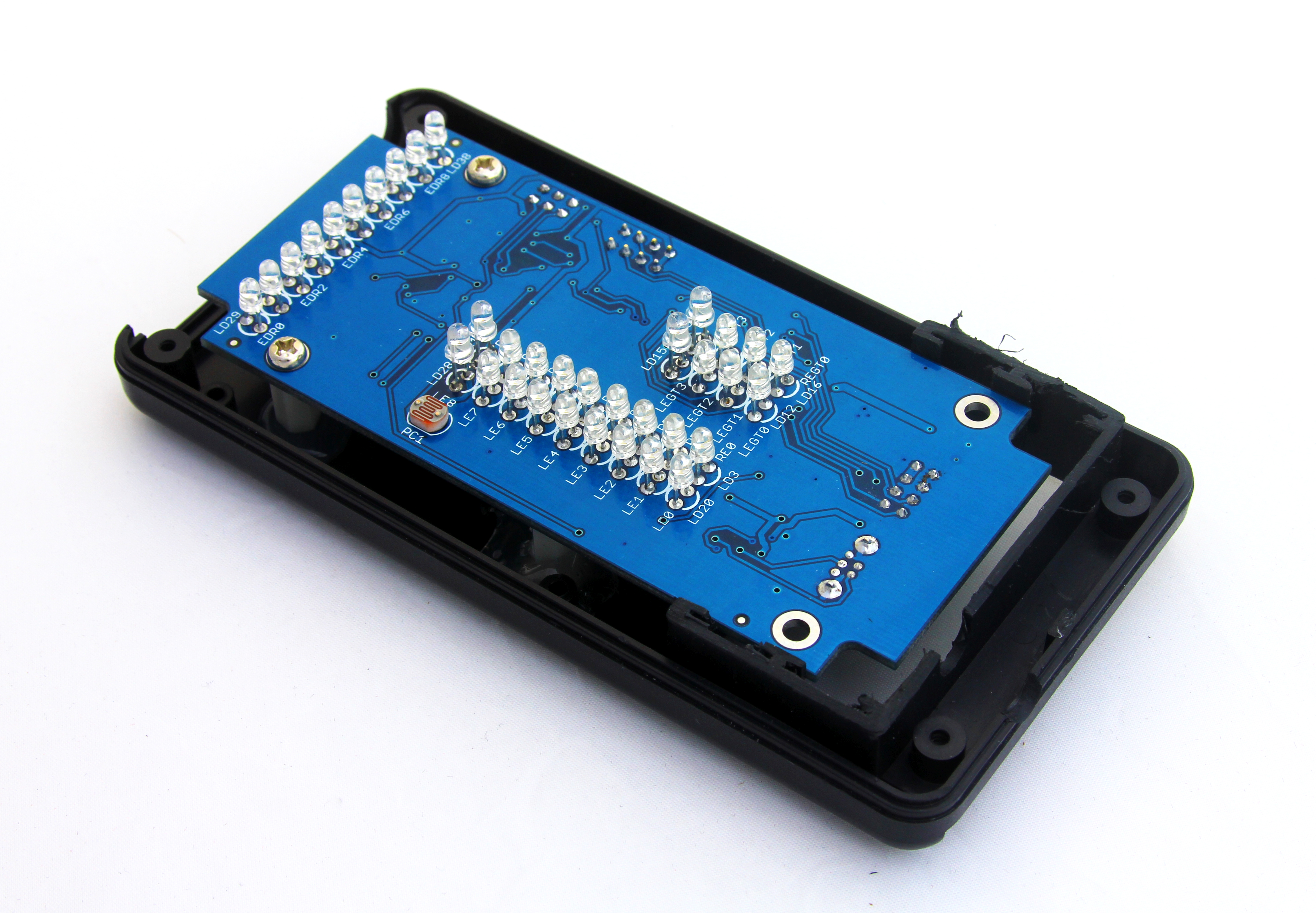
Vodafone K4606

Vodafone K4606

Acknowledging the fact that USB modems are more demanding to host controller’s resources, we were aware that it would be highly unlikely to make even top end Arduino board talk to the Vodafone dongle. So we turned our attention to ARM based solutions like one of mbed boards and finally chose the one with USB host functionality.
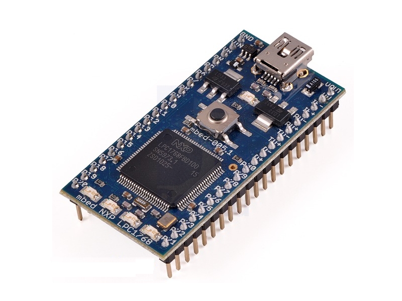
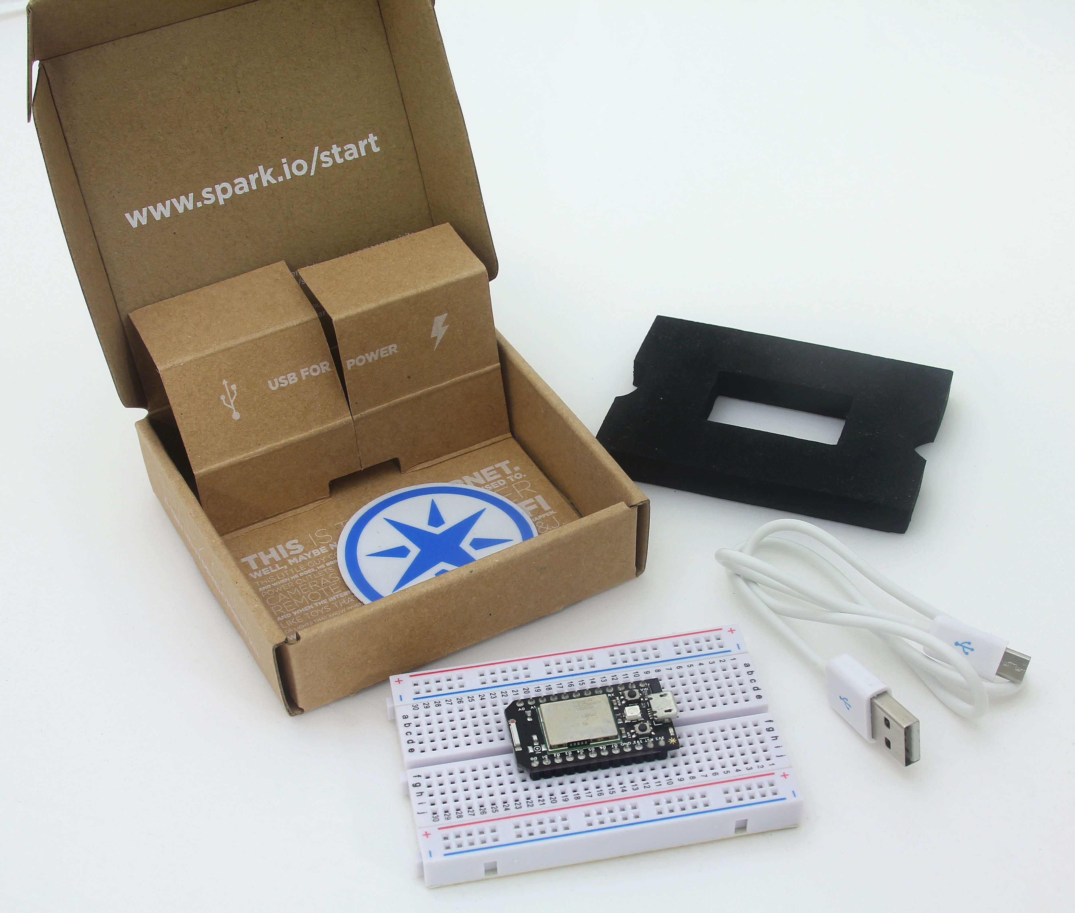
mbed LPC1768

mbed LPC1768

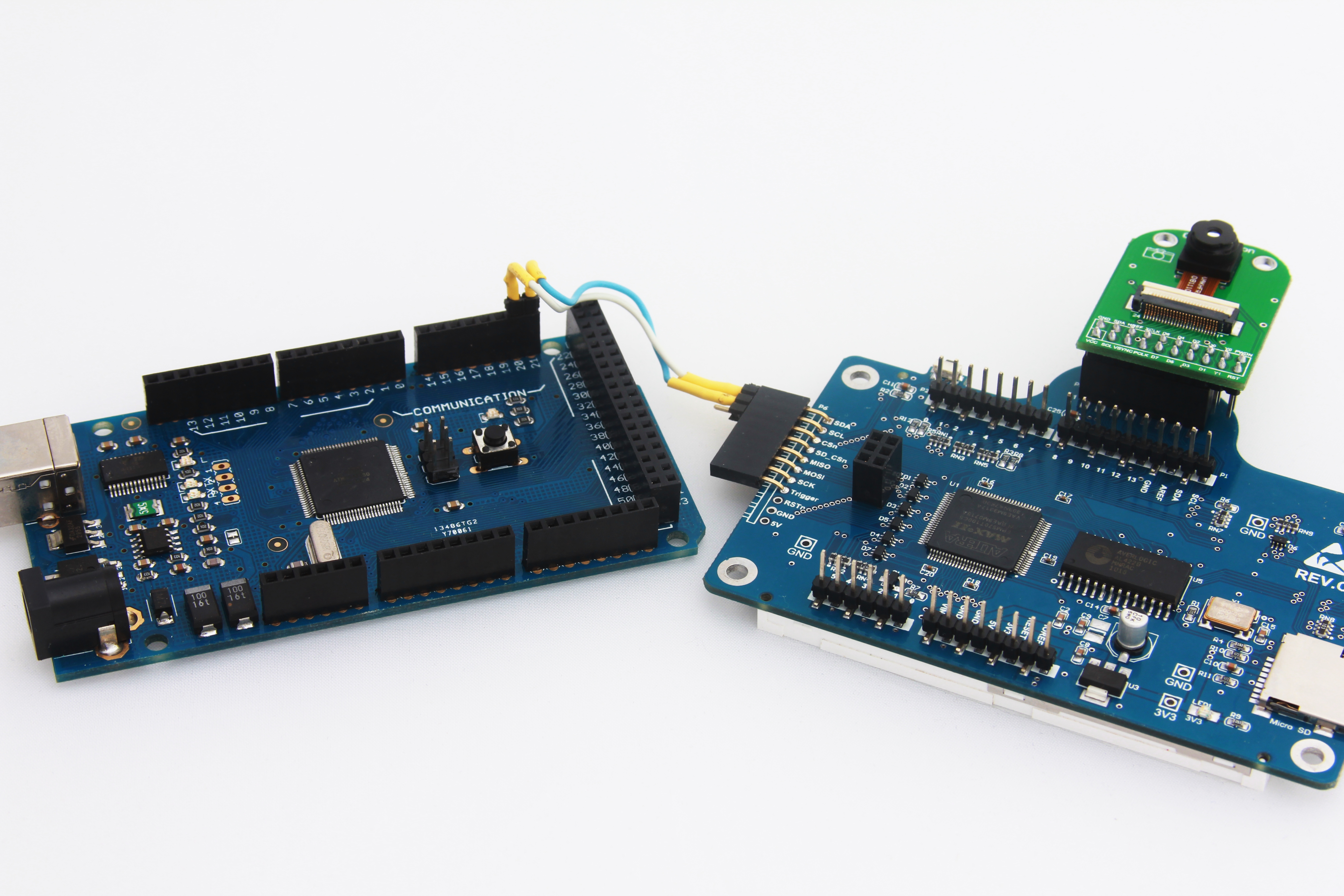
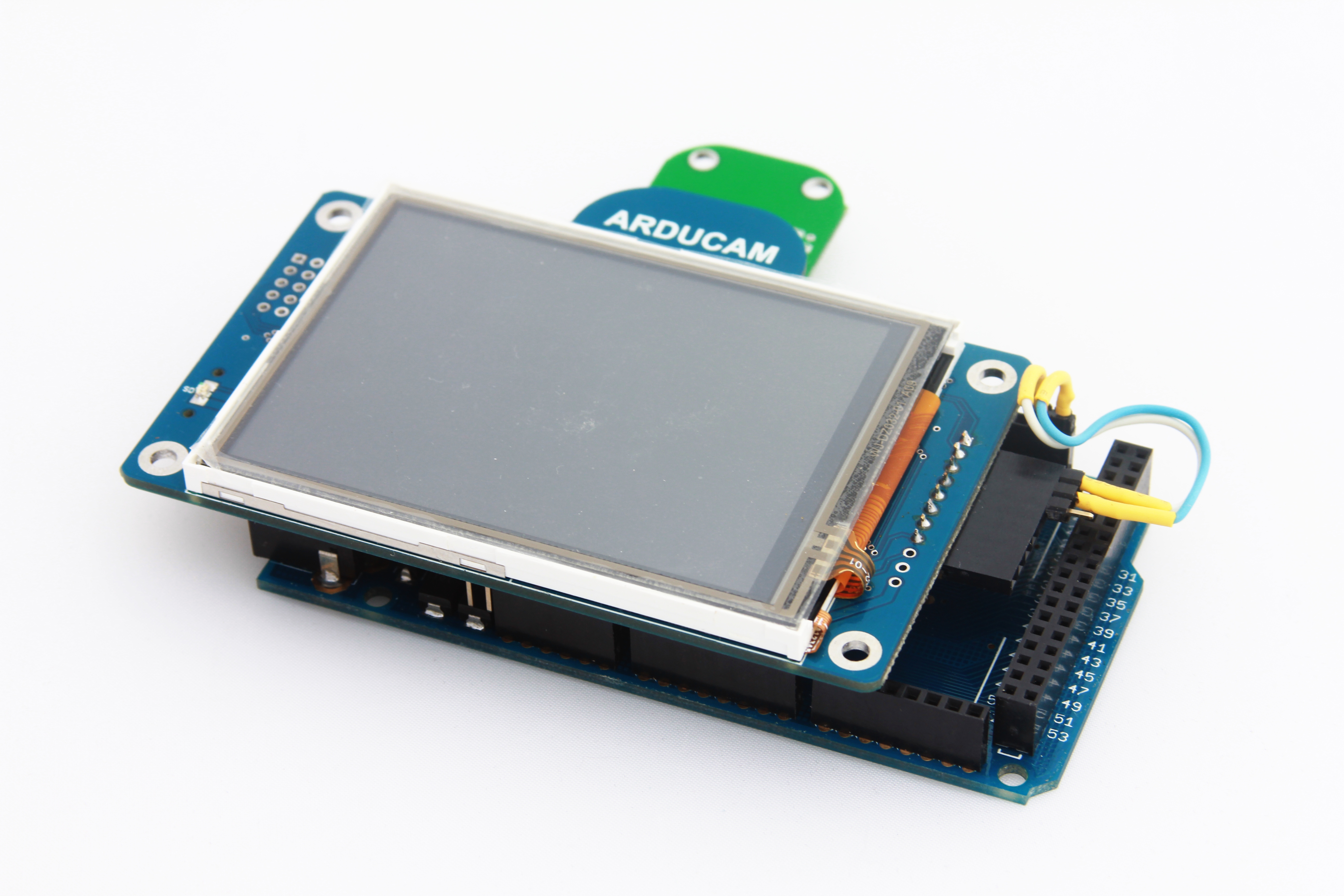
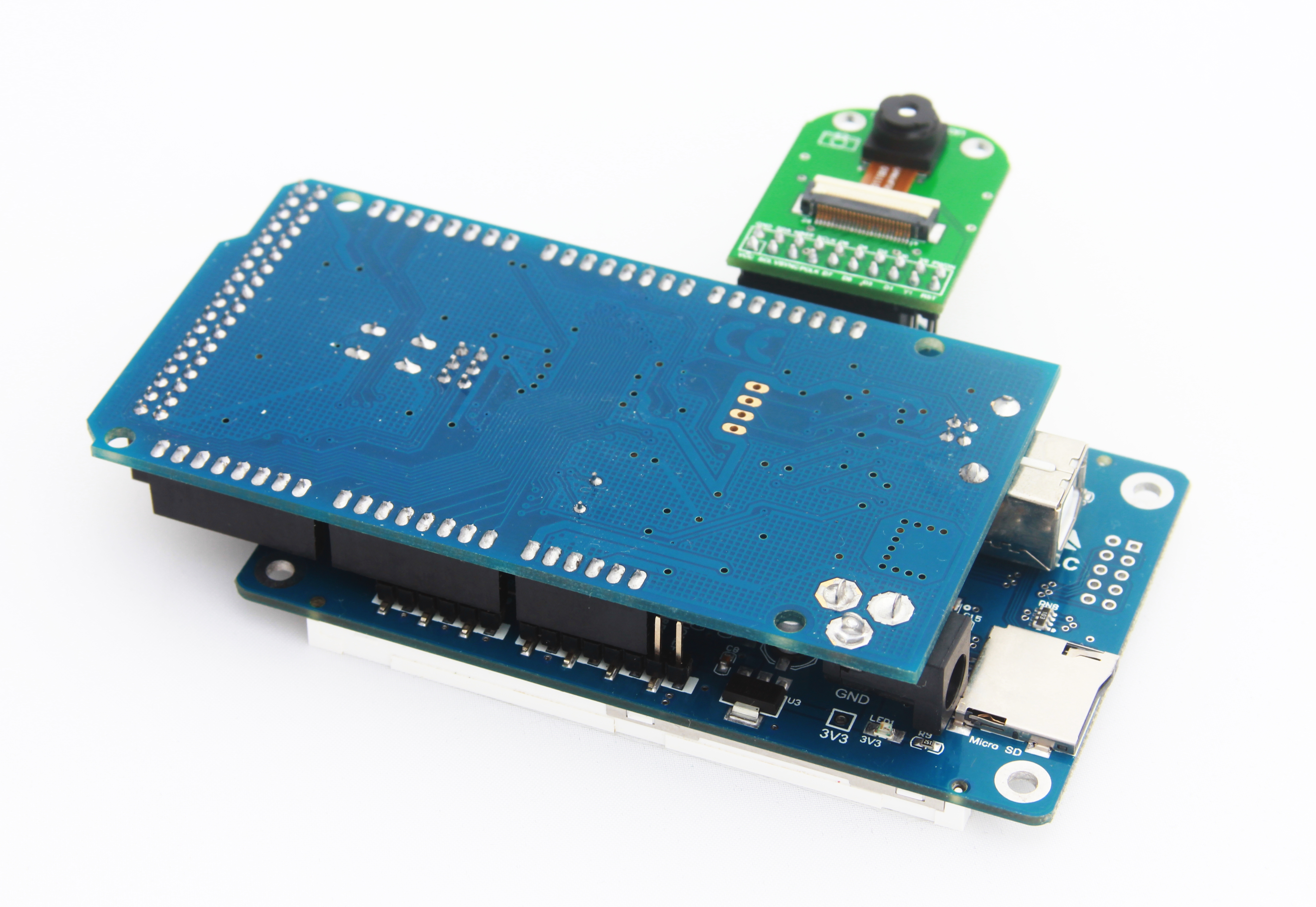
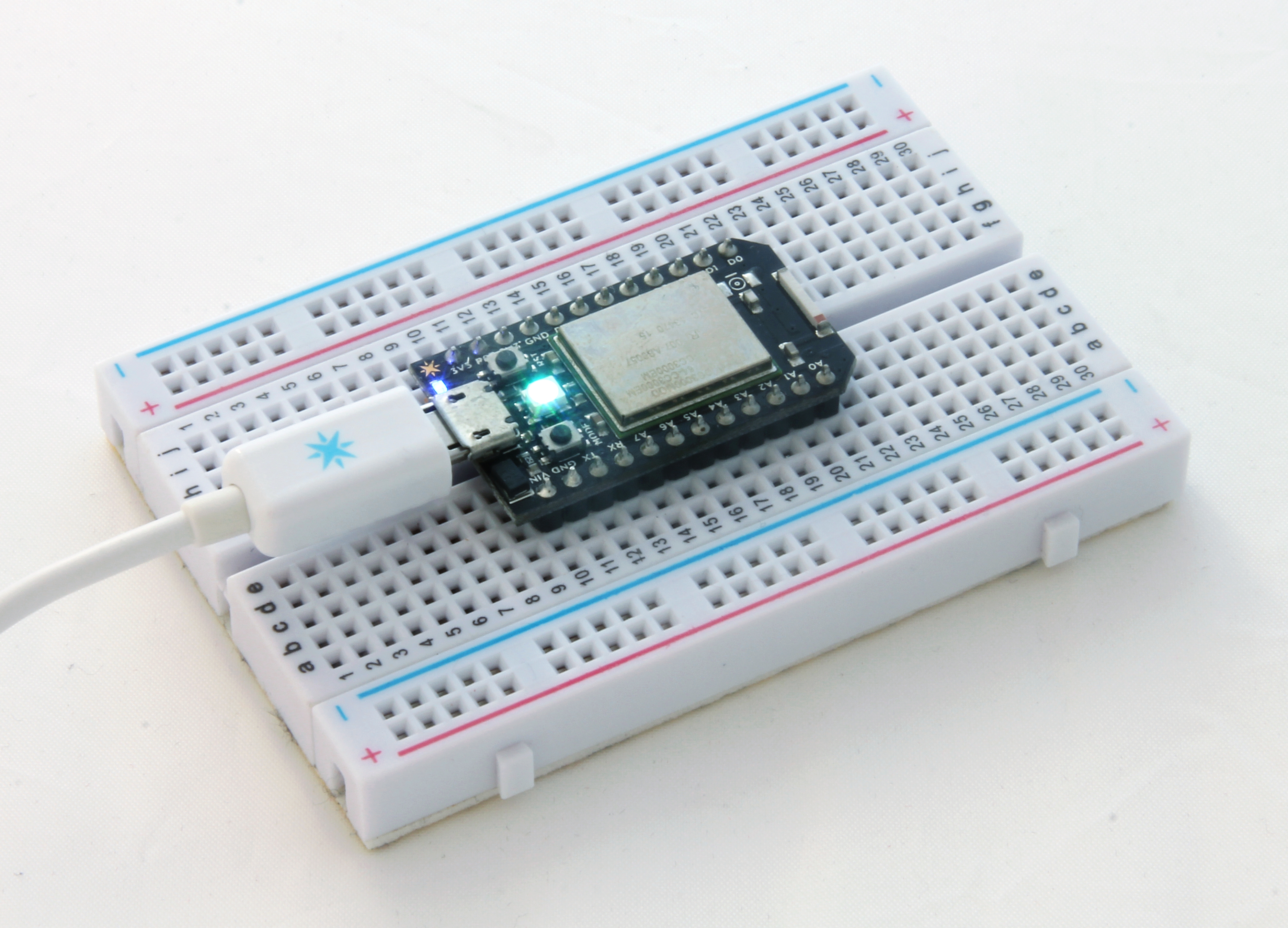
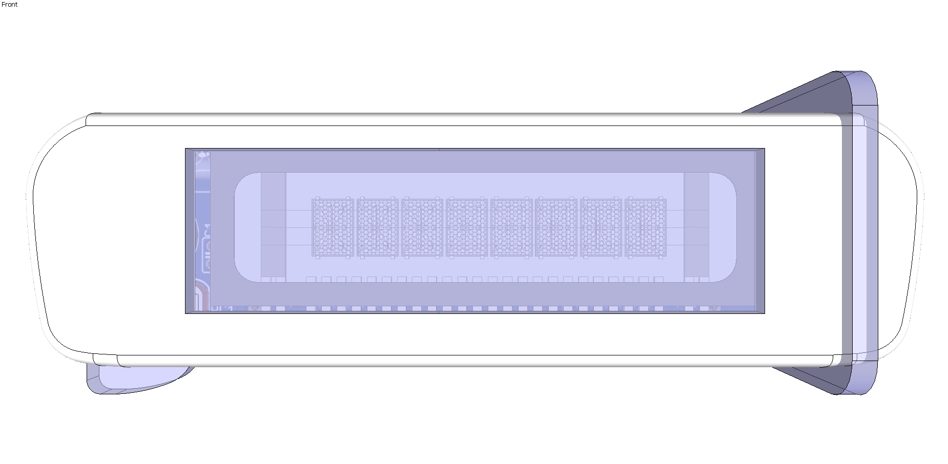
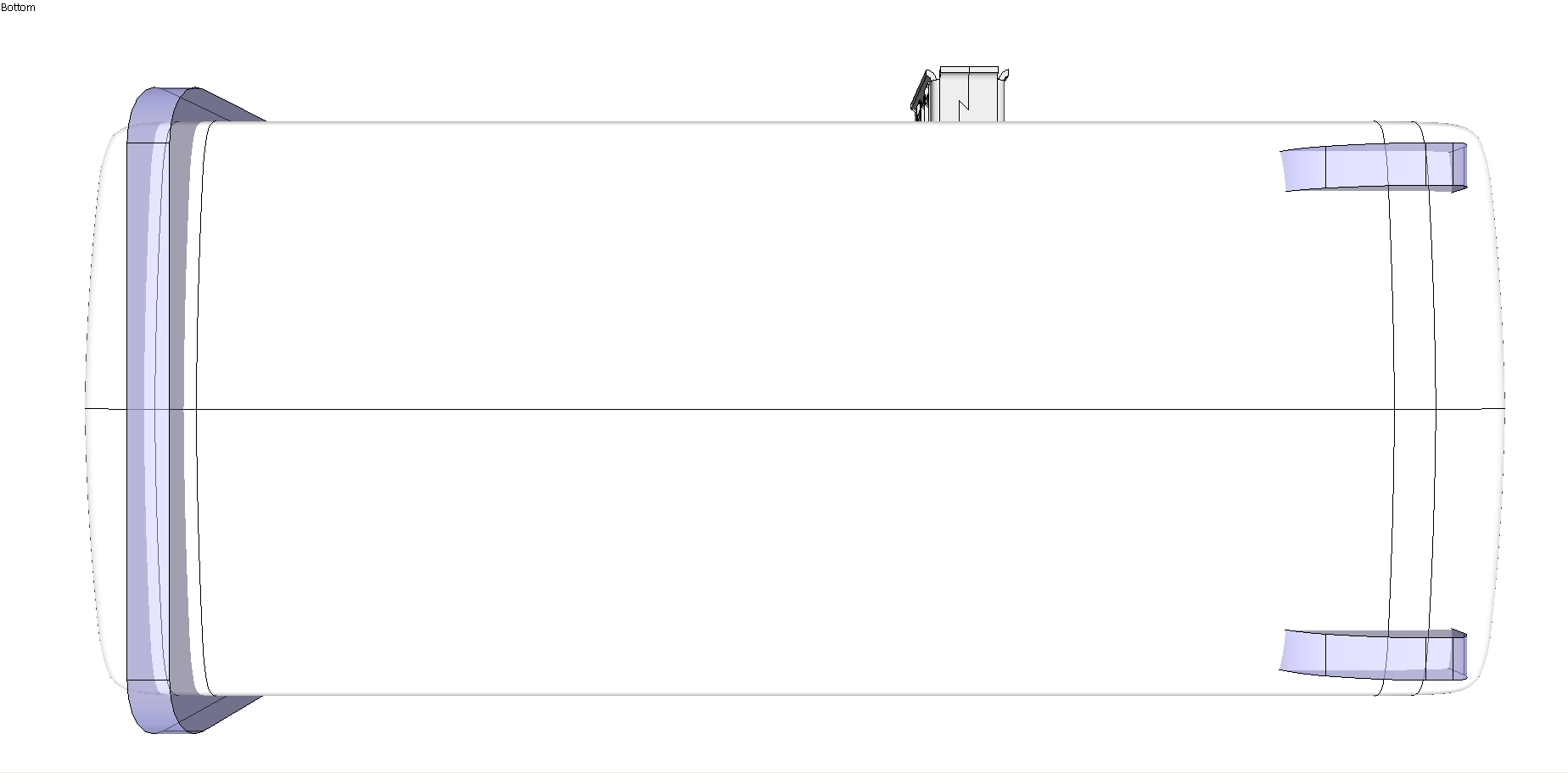
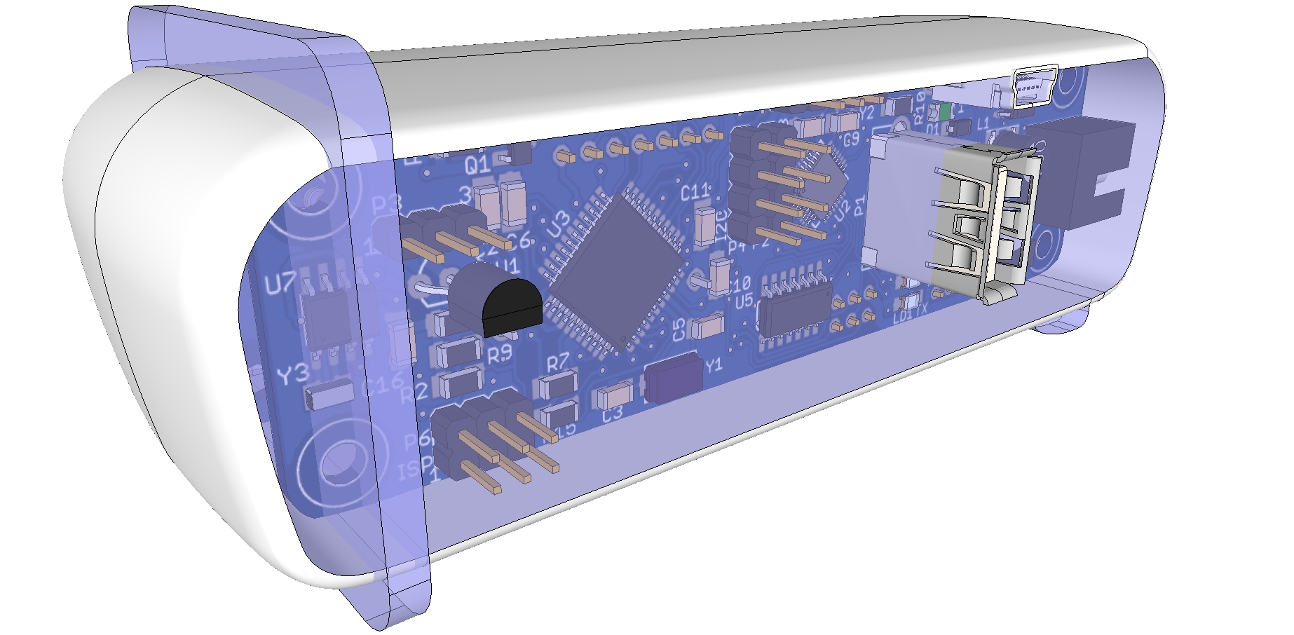
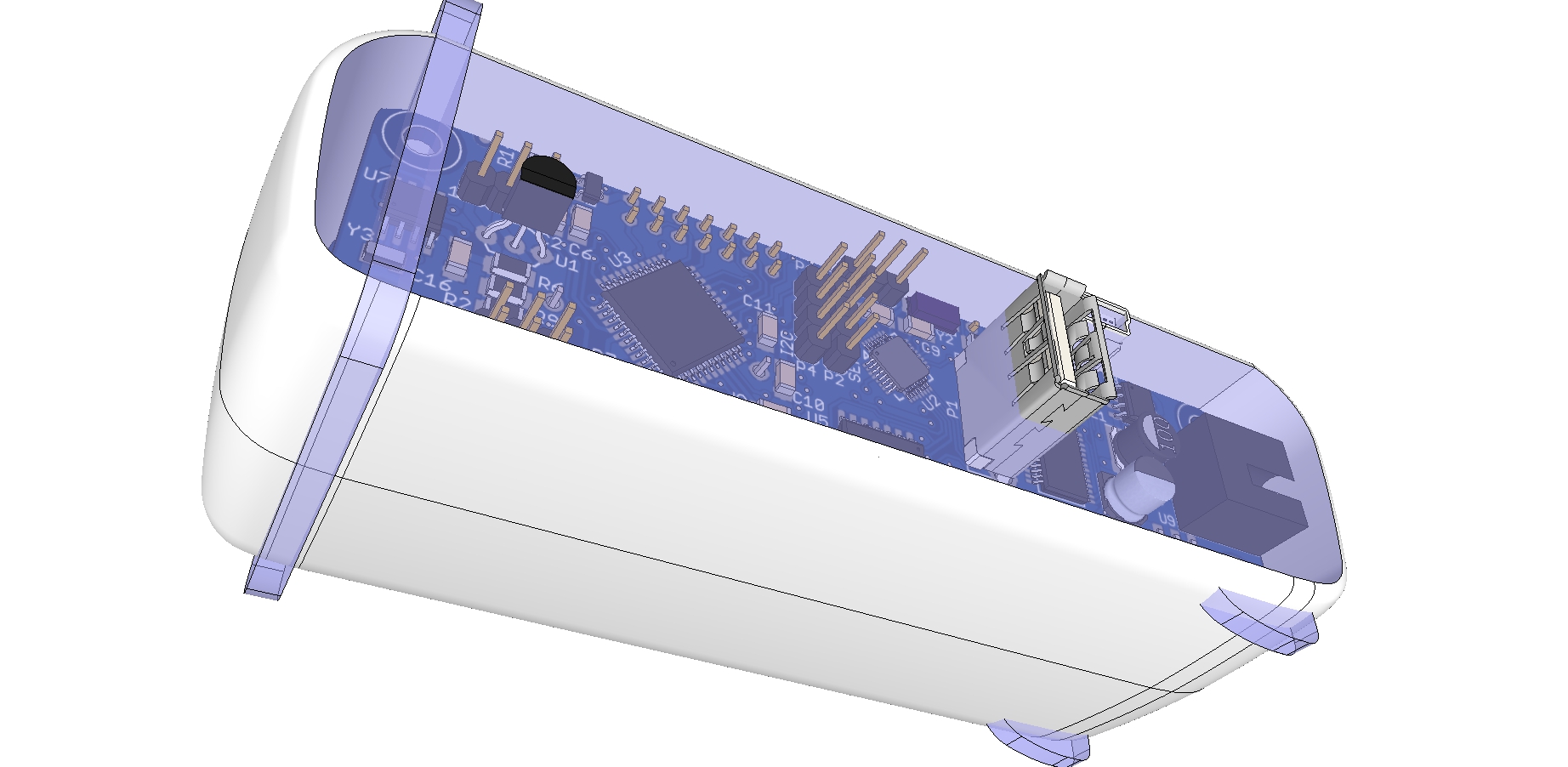
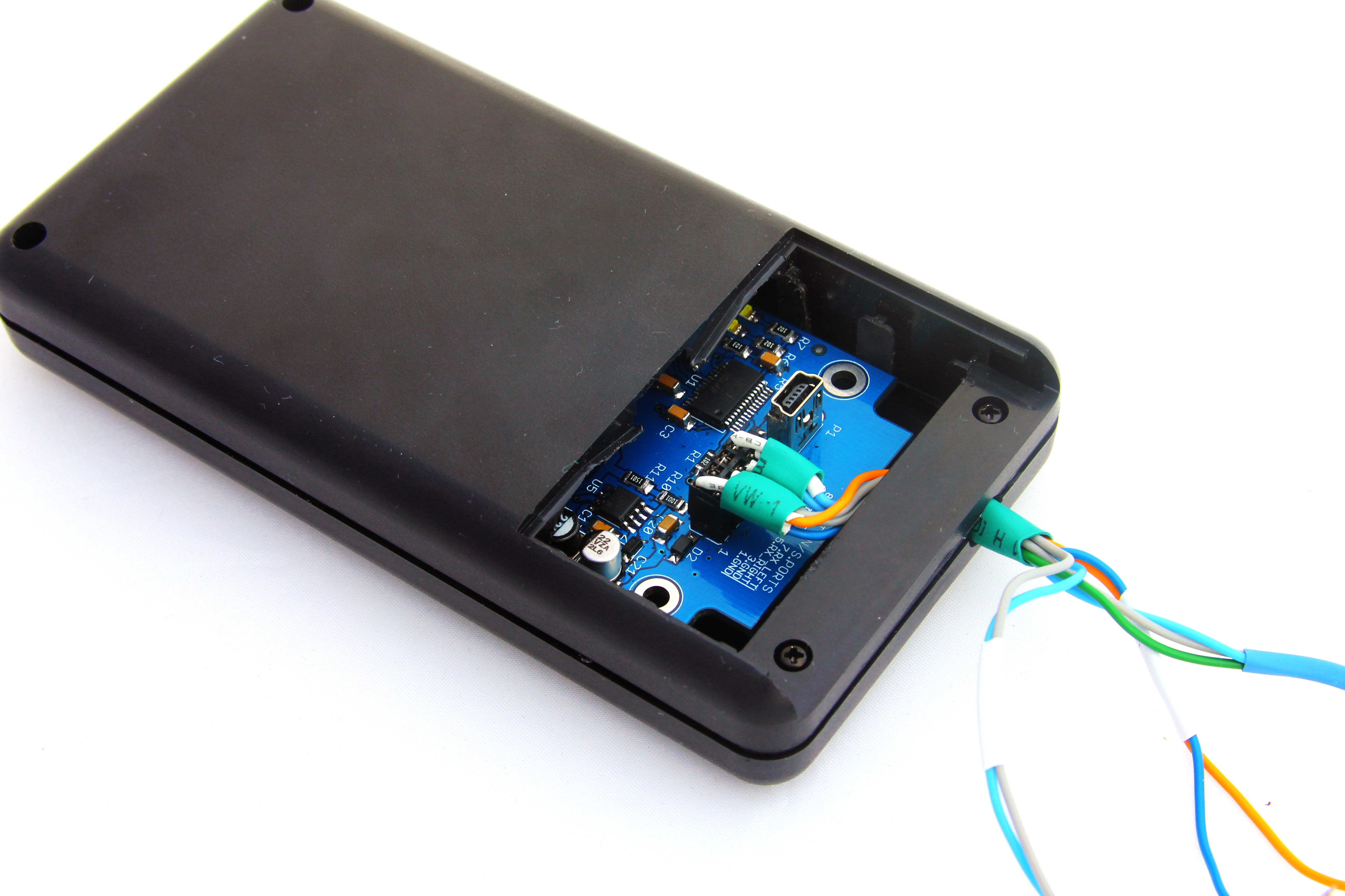
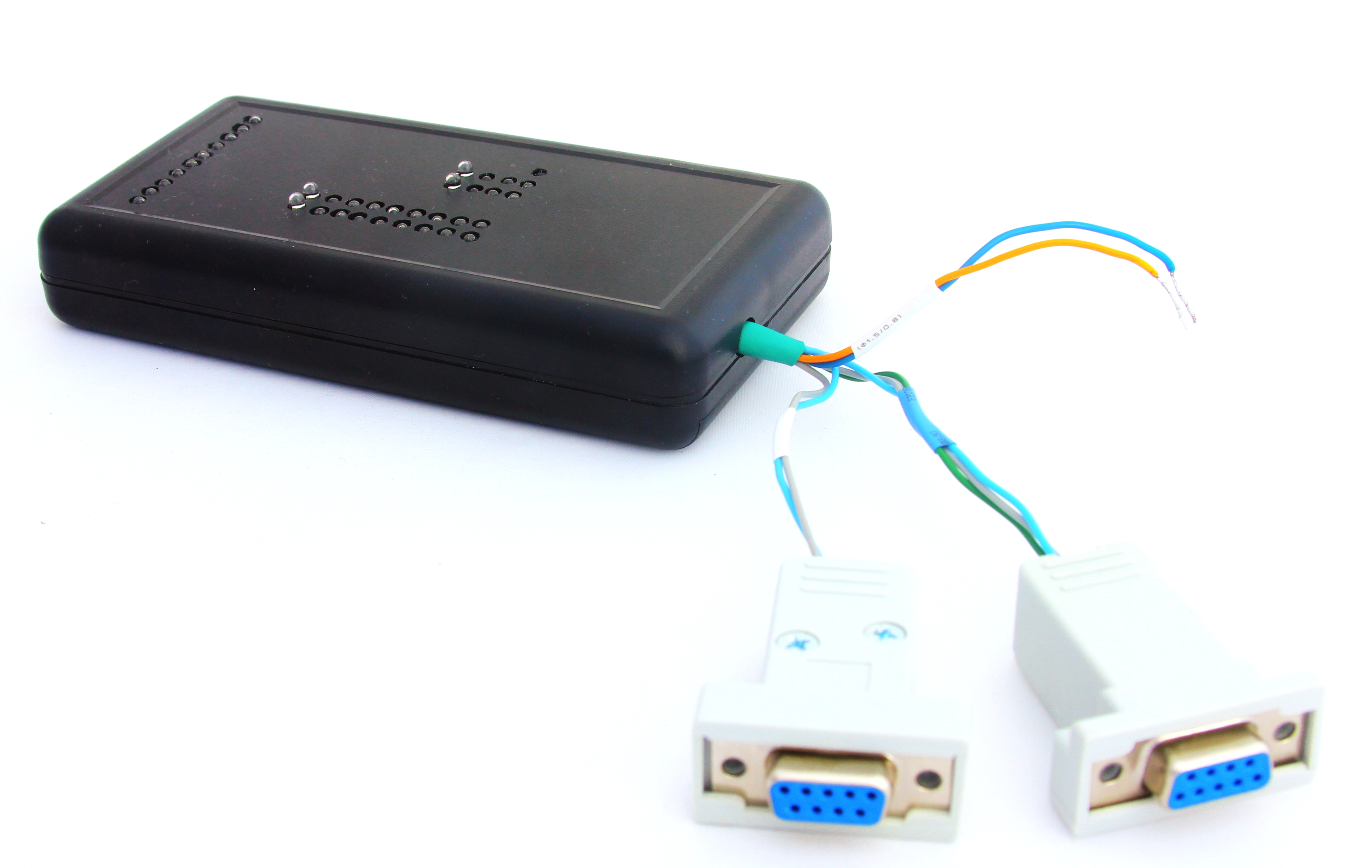
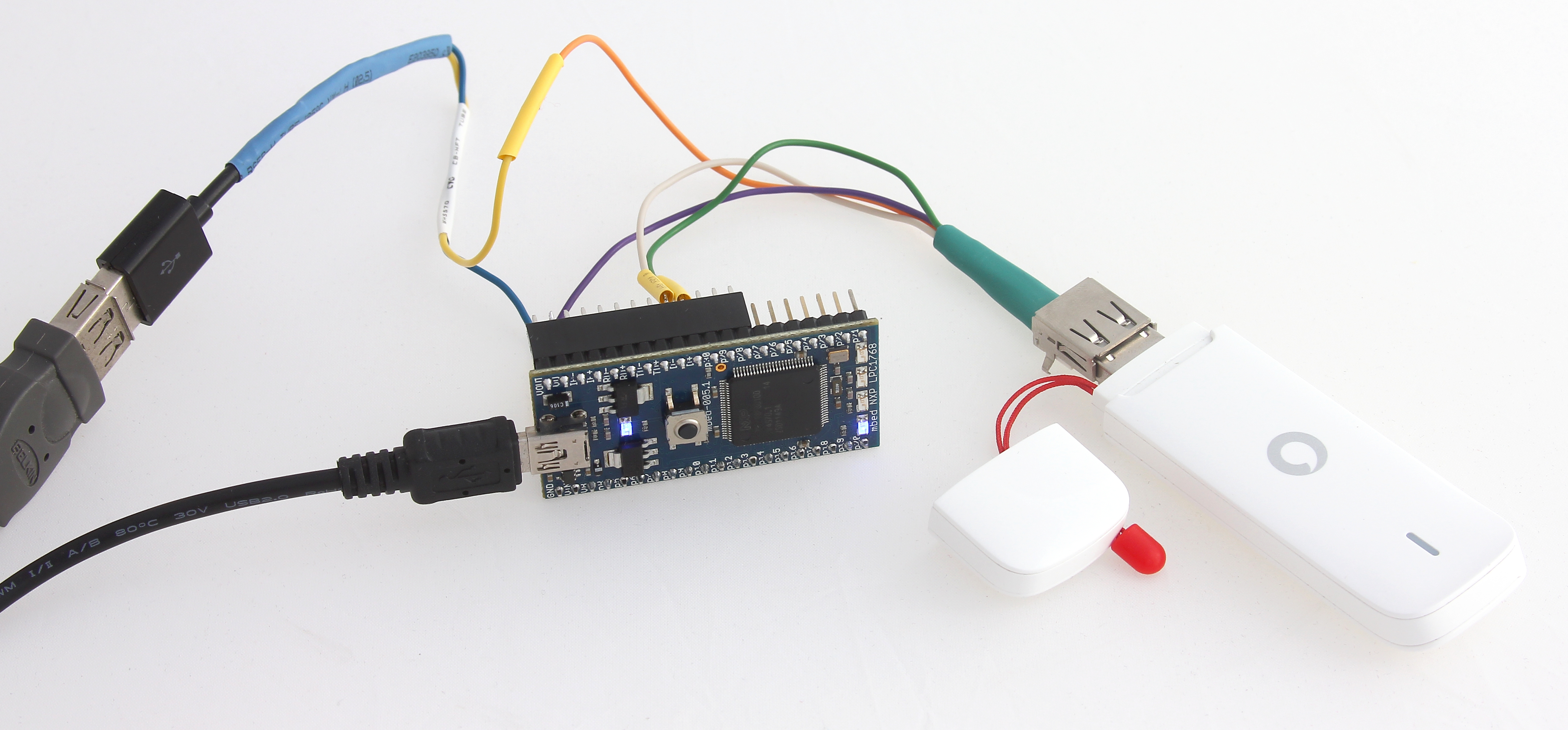
The mbed source code repository even had a fully functional library for interfacing with Vodafone mode; however, we didn’t have high hopes (and this turned to be the case shortly after) that it would immediately work with our modem. But before using USB port a few extra components including USB connector need to be wired. This is described in detail at VodafoneUSMModem Cookbook. Given that we were working on a prototype we took the risk of not using two pulldown resistors and to be honest haven’t noticed any detrimental effects during our experiments. Ignoring the advice to power USB modem separately resulted in spurious resets of mbed board so eventually we derived +5V from the second USB port. The final prototype ready for experiments is given below.

Vodafone K4606 Under Test

Vodafone K4606 Under Test

As a next step, VodafoneUSBModemHTTPClientTest - main.cpp along with the VodafoneUSBLibrary has been imported into mbed development environment. Subsequently going through all project’s folders and subfolders the underlying set of libraries has been updated to accommodate the latest changes made since the release of VodafoneUSBLibrary as show on the picture below.

VodafoneUSBModemHTTPClientTest After Project Import

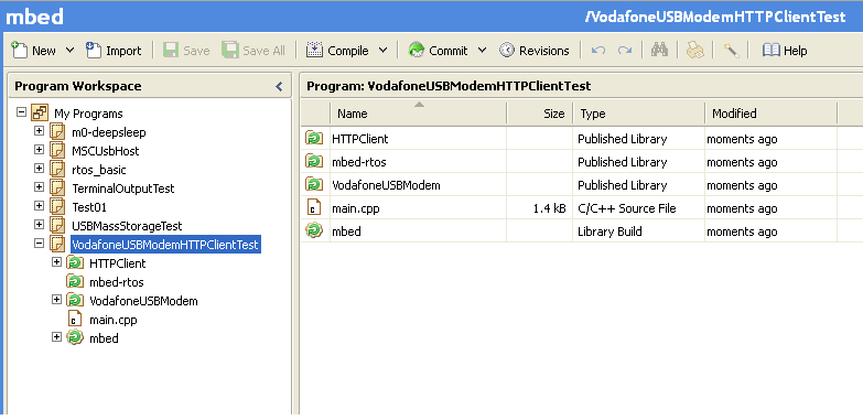
VodafoneUSBModemHTTPClientTest After Project Import. Green arrow indicates that there is update avaialble

An interesting observation: updating the parent folder doesn’t cause children folders to be updated as well – it has to be done manually as shown on the picture below.

VodafoneUSBModemHTTPClientTest Updates Available

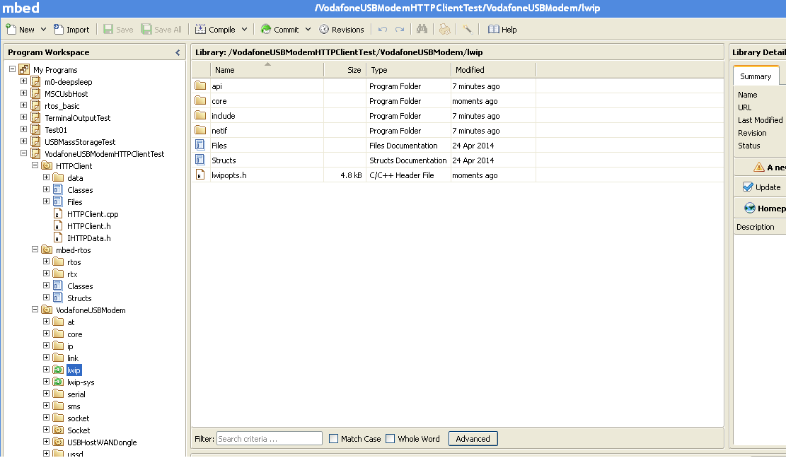
VodafoneUSBModemHTTPClientTest Updates Available. Update of the parent folder doesn’t cause children folder to be updated.

Eventually the code got into compilable state. It is fair to say that USB modem requires quite substantial bit of functionality on host controller. It includes USB Host and TCP stacks, PPP client along with CHAP/PAP authentications, DHCP client, TCP/UDP socket implementation, network streams and so on.

VodafoneUSBModemHTTPClientTest Successful Compilation

VodafoneUSBModemHTTPClientTest Successful Compilation

Before running the code APN was replaced with Australian Vodafone settings in Main.cpp

int ret = modem.connect("live.vodafone.com");

The compiled code then was uploaded to mbed board for the first time. As expected, nothing worked. There was nothing happening in terminal application so we added one more line in VodafoneUSBModem/core/dbg.h:

...
#ifdef __cplusplus
extern "C" {
#endif

#define __DEBUG__ 4

void debug_init(void);
...

… and immediately got plenty of useful information:

The most interesting output is given below. The driver was trying to detect modem type by discovered device’s VID and PID and obviously it didn’t know anything about our modem model. What has also become obvious after quick analysis of the output and source code was that the driver was designed to retrieve information about USB interfaces and endpoints slightly different depending on the modem type. In addition, upon being powered up, each modem initially works as USB mass storage device allowing to install device drivers and then it is switched to modem mode by a unique byte sequence. So as a bare minimum for our dongle it was necessary to implement its own initialiser and find out its unique combination of bytes to make it act as a modem.

[START]
...
[WARN] Module USBHALHost.cpp - Line 351: Device connected!!
...
[DBG] Module USBHost.cpp - Line 621: CLASS: 00   VID: 12D1       PID: 1F19
[DBG] Module WANDongle.cpp - Line 195: *initializer=100005e0
[DBG] Module WANDongle.cpp - Line 196: (*initializer)->getSerialVid()=12d1
[DBG] Module WANDongle.cpp - Line 197: (*initializer)->getSerialPid()=14c9
[DBG] Module WANDongle.cpp - Line 195: *initializer=100005f4
[DBG] Module WANDongle.cpp - Line 196: (*initializer)->getSerialVid()=19d2
[DBG] Module WANDongle.cpp - Line 197: (*initializer)->getSerialPid()=1181
[DBG] Module WANDongle.cpp - Line 195: *initializer=10000608
[DBG] Module WANDongle.cpp - Line 196: (*initializer)->getSerialVid()=12d1
[DBG] Module WANDongle.cpp - Line 197: (*initializer)->getSerialPid()=14cf
[DBG] Module WANDongle.cpp - Line 195: *initializer=1000061c
[DBG] Module WANDongle.cpp - Line 196: (*initializer)->getSerialVid()=12d1
[DBG] Module WANDongle.cpp - Line 197: (*initializer)->getSerialPid()=1506
[DBG] Module WANDongle.cpp - Line 195: *initializer=10000630
[DBG] Module WANDongle.cpp - Line 196: (*initializer)->getSerialVid()=12d1
[DBG] Module WANDongle.cpp - Line 197: (*initializer)->getSerialPid()=1001
[DBG] Module WANDongle.cpp - Line 195: *initializer=10000640
[DBG] Module WANDongle.cpp - Line 196: (*initializer)->getSerialVid()=1546
[DBG] Module WANDongle.cpp - Line 197: (*initializer)->getSerialPid()=1102
...
[DBG] Module USBHost.cpp - Line 645: device enumerated!!!!
[DBG] Module WANDongle.cpp - Line 80: Device has VID:12d1 PID:1f19
[DBG] Module VodafoneUSBModem.cpp - Line 527: Trying to connect the dongle
...

Searching through the internet we found that people had already discovered what the magic byte sequence was. They also provided dongles’s PID and VID for modem mode:

daxzor:

“The K4606 can also be switched to a regular modem by sending it:

55534243123456780000000000000011060000000000000000000000000000

The new id will be 12d1:1001 so the TargetProduct should be 0x1001”

Then we enhanced WANDongleInitializer.cpp with a new VodafoneK4606Initializer class taking K3773 as a base. Apart from just adding new initialiser there was one more problem to mitigate – a Huawei MU509 modem which had the same Vid:Pid combination in serial mode (12d1:1001) so after switching to serial mode the driver didn’t keep track on what was discovered before and simply kept picking up wrong initialiser. The issue was addressed by adding m_lastDongle in WANDongle.cpp, the modified files are available here. With the two enhancements the output became as shown on the video below:

Newly generated debug output (shown below) suggested that this time the modem was successfully switched to serial mode, correctly detected as K4606 so that its Vid:Pid pair become 12D1:1001 as expected, then the driver discovered three interfaces but skipped all endpoints that is why when it tried to connect serial ports both endpoints were returned as ‘Ep 00000000’ – means NULL pointers or, in other words, not initialised.

[START]
...
[DBG] Module USBHost.cpp - Line 621: CLASS: 00   VID: 12D1       PID: 1F19
[DBG] Module WANDongle.cpp - Line 204: *initializer=100021f4
[DBG] Module WANDongle.cpp - Line 205: (*initializer)->getSerialVid()=12d1
[DBG] Module WANDongle.cpp - Line 206: (*initializer)->getSerialPid()=14c9
[DBG] Module WANDongle.cpp - Line 204: *initializer=10002208
[DBG] Module WANDongle.cpp - Line 205: (*initializer)->getSerialVid()=19d2
[DBG] Module WANDongle.cpp - Line 206: (*initializer)->getSerialPid()=1181
[DBG] Module WANDongle.cpp - Line 204: *initializer=1000221c
[DBG] Module WANDongle.cpp - Line 205: (*initializer)->getSerialVid()=12d1
[DBG] Module WANDongle.cpp - Line 206: (*initializer)->getSerialPid()=14cf
[DBG] Module WANDongle.cpp - Line 204: *initializer=10002230
[DBG] Module WANDongle.cpp - Line 205: (*initializer)->getSerialVid()=12d1
[DBG] Module WANDongle.cpp - Line 206: (*initializer)->getSerialPid()=1506
[DBG] Module WANDongle.cpp - Line 204: *initializer=10002244
[DBG] Module WANDongle.cpp - Line 205: (*initializer)->getSerialVid()=12d1
[DBG] Module WANDongle.cpp - Line 206: (*initializer)->getSerialPid()=1001
[DBG] Module WANDongle.cpp - Line 204: *initializer=10002254
[DBG] Module WANDongle.cpp - Line 205: (*initializer)->getSerialVid()=1546
[DBG] Module WANDongle.cpp - Line 206: (*initializer)->getSerialPid()=1102
[DBG] Module WANDongle.cpp - Line 204: *initializer=10002268
[DBG] Module WANDongle.cpp - Line 205: (*initializer)->getSerialVid()=12d1
[DBG] Module WANDongle.cpp - Line 206: (*initializer)->getSerialPid()=1001
...
[DBG] Module USBHost.cpp - Line 776: !!!!!!!!!!!!! bulkwrite finished
[DBG] Module WANDongle.cpp - Line 120: Switched OK
[DBG] Module VodafoneUSBModem.cpp - Line 527: Trying to connect the dongle
[DBG] Module WANDongle.cpp - Line 48: Trying to connect device
[WARN] Module USBHALHost.cpp - Line 351: Device connected!!
...
[DBG] Module USBHost.cpp - Line 621: CLASS: 00   VID: 12D1       PID: 1001
[DBG] Module WANDongle.cpp - Line 198: Initializer has been already detected in previous step
...
[DBG] Module WANDongleInitializer.cpp - Line 755: *K4606 parsing intf 0, intf_class 2, m_currentSerialIntf 0
[DBG] Module USBHost.cpp - Line 687: Ep DESC
[DBG] Module USBHost.cpp - Line 687: Ep DESC
[DBG] Module USBHost.cpp - Line 687: Ep DESC
[DBG] Module WANDongleInitializer.cpp - Line 755: *K4606 parsing intf 0, intf_class 2, m_currentSerialIntf 0
[DBG] Module USBHost.cpp - Line 687: Ep DESC
[DBG] Module USBHost.cpp - Line 687: Ep DESC
[DBG] Module WANDongleInitializer.cpp - Line 755: *K4606 parsing intf 0, intf_class 2, m_currentSerialIntf 0
[DBG] Module USBHost.cpp - Line 687: Ep DESC
[DBG] Module USBHost.cpp - Line 687: Ep DESC
...
[DBG] Module WANDongle.cpp - Line 81: Device has VID:12d1 PID:1001
[DBG] Module WANDongle.cpp - Line 85: m_pInitializer=10002268
[DBG] Module WANDongle.cpp - Line 86: m_pInitializer->getSerialVid()=12d1
[DBG] Module WANDongle.cpp - Line 87: m_pInitializer->getSerialPid()=1001
[DBG] Module WANDongle.cpp - Line 90: The dongle is in virtual serial mode
[DBG] Module WANDongle.cpp - Line 93: Num serial ports: 2
[DBG] Module WANDongle.cpp - Line 101: Connecting serial port #1
[DBG] Module WANDongle.cpp - Line 102: Ep 00000000
[DBG] Module WANDongle.cpp - Line 103: Ep 00000000

At this stage it is, perhaps, worthwhile to give a bit of theory. Normally, a generic modem has just one serial port. However, this modem had two serial ports, each one was represented by one interface, each interface, in its own turn, had two endpoints, inbound and outbound datastreams. One serial port was intended for use by AT commands and the other one was for PPP transport. As we already noticed, this modem had three interfaces, not just two, and most probably the third one was for uploading firmware updates or something like that, the good news was that we wouldn’t need it. So our next task was to decide which two interfaces out of three to pick, which endpoints are for writing data and which are for reading data. Eventually we found (as we thought) the right combination, the changes are highlighted below:

bool VodafoneK4606Initializer::parseInterface(uint8_t intf_nb, uint8_t intf_class, uint8_t intf_subclass, uint8_t intf_protocol) //Must return true if the interface should be parsed
{
  if( m_hasSwitched )
  {
    DBG("*K4606 parsing intf %d, intf_class %d, m_currentSerialIntf %d", intf_nb, intf_class, m_currentSerialIntf);    
    
    if( intf_class == 0xFF )
    {
      if( (m_currentSerialIntf == 0) || (m_currentSerialIntf == 4) )
      {
        m_currentSerialIntf++;
        return true;
      }
      m_currentSerialIntf++;
    }
  }
  else
  {
    if( (intf_nb == 0) && (intf_class == MSD_CLASS) )
    {
      return true;
    }
  }
  return false;
}

It also has been noticed that with debug output enabled application kept stopping working at some arbitrary point in time displaying ‘blue lights of death’. With the baudrate ramped up from 9600bps to 460800bps the problem went away and never occured again. Here are the changes than needed to be done in order to charge baudrate:

#include "mbed.h"
#include "VodafoneUSBModem.h"
#include "HTTPClient.h"

#define DBG_PORT_BAUD 460800
Serial pc(USBTX, USBRX);

void test(void const*) 
{
...
}


int main()
{
  pc.baud (DBG_PORT_BAUD);  
  Thread testTask(test, NULL, osPriorityNormal, 1024 * 4);
  DigitalOut led(LED1);
  while(1)
  {
    led=!led;
    Thread::wait(1000);  
  }

  return 0;
}

Resulted debug output of the third experiment with correctly parsed and used interfaces and endpoints is given below:

After filtering important lines from the third experiment debug we got the following list. It is clearly seen that interfaces and their endpoints were parsed, both serial ports were successfully opened, modem was initialised, APN was set but for some reasons PPP failed to open. Given that the host controller didn’t receive a single byte in reply to the very first PPP packet there were really two potential reasons for that: either nobody was listening on a remote side or communication channel just didn’t work.

[START]
...
[DBG] Module WANDongleInitializer.cpp - Line 717: Vodafone K4606 MSD descriptor found on device 100039b0, intf 0, will now try to switch into serial mode
...
[DBG] Module WANDongle.cpp - Line 120: Switched OK
...
[DBG] Module WANDongleInitializer.cpp - Line 755: *K4606 parsing intf 0, intf_class 2, m_currentSerialIntf 0
[DBG] Module USBHost.cpp - Line 675: ADD INTF 0 on device 100039b0: class: 2, subclass: 2, proto: 255
...
[DBG] Module USBHost.cpp - Line 311: USBEndpoint created (10003870): type: 2, dir: 2, size: 64, addr: 2
[DBG] Module USBHost.cpp - Line 698: ADD USBEndpoint 10003870, on interf 0 on device 100039b0
[DBG] Module USBHost.cpp - Line 337: New ep 10003870
...
[DBG] Module USBHost.cpp - Line 311: USBEndpoint created (100038b8): type: 2, dir: 1, size: 64, addr: 1
[DBG] Module USBHost.cpp - Line 698: ADD USBEndpoint 100038b8, on interf 0 on device 100039b0
[DBG] Module USBHost.cpp - Line 337: New ep 100038b8
[DBG] Module WANDongleInitializer.cpp - Line 755: *K4606 parsing intf 1, intf_class 2, m_currentSerialIntf 1
...
[DBG] Module WANDongleInitializer.cpp - Line 755: *K4606 parsing intf 1, intf_class 2, m_currentSerialIntf 2
[DBG] Module USBHost.cpp - Line 675: ADD INTF 1 on device 100039b0: class: 2, subclass: 2, proto: 255
...
[DBG] Module USBHost.cpp - Line 311: USBEndpoint created (10003900): type: 2, dir: 2, size: 64, addr: 4
[DBG] Module USBHost.cpp - Line 698: ADD USBEndpoint 10003900, on interf 1 on device 100039b0
[DBG] Module USBHost.cpp - Line 337: New ep 10003900
...
[DBG] Module USBHost.cpp - Line 311: USBEndpoint created (10003948): type: 2, dir: 1, size: 64, addr: 3
[DBG] Module USBHost.cpp - Line 698: ADD USBEndpoint 10003948, on interf 1 on device 100039b0
[DBG] Module USBHost.cpp - Line 337: New ep 10003948
...
[DBG] Module USBHost.cpp - Line 645: device enumerated!!!!
[DBG] Module WANDongle.cpp - Line 81: Device has VID:12d1 PID:1001
...
[DBG] Module WANDongle.cpp - Line 90: The dongle is in virtual serial mode
[DBG] Module WANDongle.cpp - Line 93: Num serial ports: 2
[DBG] Module WANDongle.cpp - Line 101: Connecting serial port #1
[DBG] Module WANDongle.cpp - Line 102: Ep 10003900
[DBG] Module WANDongle.cpp - Line 103: Ep 10003948
...
[DBG] Module USBHost.cpp - Line 480: Now do queue transfer on ep 10003900
...
[DBG] Module WANDongle.cpp - Line 101: Connecting serial port #2
[DBG] Module WANDongle.cpp - Line 102: Ep 10003870
[DBG] Module WANDongle.cpp - Line 103: Ep 100038b8
...
[DBG] Module USBHost.cpp - Line 480: Now do queue transfer on ep 10003870
...
[DBG] Module VodafoneUSBModem.cpp - Line 531: Great the dongle is connected - I've tried 5 times to connect
...
[DBG] Module ATCommandsInterface.cpp - Line 69: AT interface opened
[DBG] Module VodafoneUSBModem.cpp - Line 572: Sending initialisation commands
[DBG] Module ATCommandsInterface.cpp - Line 77: Sending ATZ E1 V1
...
[DBG] Module ATCommandsInterface.cpp - Line 625: Processing read line [OK]
[DBG] Module SMSInterface.cpp - Line 327: AT code is OK
...
[DBG] Module ATCommandsInterface.cpp - Line 224: Executing command AT+CNMI=2,1,0,0,0
[DBG] Module ATCommandsInterface.cpp - Line 625: Processing read line [OK]
...
[DBG] Module ATCommandsInterface.cpp - Line 224: Executing command AT+CREG?
[DBG] Module ATCommandsInterface.cpp - Line 625: Processing read line [+CREG: 2,1,"00F7","04C7AFF2"]
[DBG] Module ATCommandsInterface.cpp - Line 677: OK result received
...
[DBG] Module ATCommandsInterface.cpp - Line 224: Executing command AT+CGDCONT=1,"IP","live.vodafone.com"
[DBG] Module ATCommandsInterface.cpp - Line 625: Processing read line [AT+CGDCONT=1,"IP","live.vodafone.com"]
[DBG] Module ATCommandsInterface.cpp - Line 677: OK result received
...
[DBG] Module VodafoneUSBModem.cpp - Line 245: APN set to live.vodafone.com
[DBG] Module VodafoneUSBModem.cpp - Line 251: Connecting
[DBG] Module VodafoneUSBModem.cpp - Line 270: Connecting PPP
...
[DBG] Module PPPIPInterface.cpp - Line 239: Sending ATH
[DBG] Module PPPIPInterface.cpp - Line 273: Got ATH
[DBG] Module PPPIPInterface.cpp - Line 287: Got
OK
...
[DBG] Module PPPIPInterface.cpp - Line 108: Sending ATD *99#
[DBG] Module PPPIPInterface.cpp - Line 134: Got ATD *99#

CONNECT
...
[DBG] Module PPPIPInterface.cpp - Line 145: Transport link open
...
[DBG] Module USBSerialStream.cpp - Line 140: Trying to write 46 chars
[DBG] Module USBSerialStream.cpp - Line 50: Trying to read at most 1504 chars
...
[DBG] Module USBSerialStream.cpp - Line 140: Trying to write 46 chars
...
[DBG] Module USBSerialStream.cpp - Line 140: Trying to write 46 chars
...
[DBG] Module USBSerialStream.cpp - Line 140: Trying to write 46 chars
...
[DBG] Module USBSerialStream.cpp - Line 140: Trying to write 46 chars
...
[DBG] Module USBSerialStream.cpp - Line 140: Trying to write 46 chars
...
[DBG] Module USBSerialStream.cpp - Line 140: Trying to write 46 chars
...
[DBG] Module USBSerialStream.cpp - Line 140: Trying to write 46 chars
...
[DBG] Module USBSerialStream.cpp - Line 151: Writing 46 chars
[DBG] Module USBSerialStream.cpp - Line 99: Aborted
...
[DBG] Module VodafoneUSBModem.cpp - Line 273: Result of connect: Err code=15
Could not connect
[DBG] Module USBSerialStream.cpp - Line 94: Timeout
[DBG] Module ATCommandsInterface.cpp - Line 344: Nothing read
...

At that point it was really unclear why PPP was unable to start so we decided to plug the modem into Linux machine and using Wireshark sniff USB traffic in order to find what we were doing differently. We didn’t realise how much there was yet to be discovered and how simple the final change would be.

USB traffic captured by Wireshark is shown below. The dongle was plugged into USB port shortly after the start of the capturing application. The modem successfully connected to the Internet and Kubuntu recognised the hardware without need to install drivers or doing something manually. However, two strange things have been discovered. First of all, from OS point of view, the hardware was not a modem but rather a wired Enternet adapter. Secondly, after filtering and analysing USB packets it turned out that the very last packet when Kubuntu was talking to the dongle as to a Mass Storage Device (MSD) was a byte sequence… slightly different from the one we used in order to switch the dongle to modem mode. By the look of things, the dongle could pretend to be not only Mass Storage Device or modem but also as an Ethernet adapter. And if so, we needed to use the other byte sequence in order to force the dongle to switch to modem mode and only then try to establish Internet connection again.

What was happening on a Linux machine after plugging in Vodafone modem with default settings is shown in video below. lsusb -t command indicated that the dongle was recognised as 'cdc_ether'. Shortly after ifconfig displayed one more additional Ethernet interface eth1. dmesg suggested that after mode switch the dongle had Vid:Pid combination set to 12d1:157b.

By forcing the dongle to switch to modem mode result was quite different. lsusb -t command indicated that the dongle was recognised but no appropriate driver was loaded. No additional interface appeared in the list generated by ifconfig. dmesg suggested that after mode switch the dongle had Vid:Pid combination set to 12d1:1001 (just what we had during our experiments with mbed board!)

Then it took us some time to understand how to load correct driver for modem mode. We were stuck until we found this discussion and an original way of solving the problem:

bmork:
which is good in the sense that it confirms that no driver has captured any of the interfaces. If the modem really has vid:pid = 12d1:1c05, then something *should* happen when you type:

Code:
echo 12d1 1c05 >/sys/bus/usb-serial/drivers/option1/new_id

If you have Linux v3.5 or later, then you can verify the list of dynamically added IDs by doing

Code:
cat /sys/bus/usb-serial/drivers/option1/new_id

Finally Linux loaded the driver and assigned three interfaces to ttyUSB0, ttyUSB1 and ttyUSB2. After that the only remaining part was to configuire wvdial and run it watching how PPP interface was being established. Then by opening new terminal it became obvious that ifconfig reported one additional ppp0 network interface and the Internet connection was wokring again, this time via the dongle in modem mode.

Remarkably, that wvdial used only one ttyUSB0 port for AT commands and PPP transport. Suddenly we were stunned – what if iterfaces for AT and PPP are not interchangeable and we inadvertently swapped them, could it explain why our mbed board kept failing to open PPP? All we needed to do was to replace just one line with the following content:

USBEndpoint* VodafoneK4606Initializer::getEp(USBDeviceConnected* pDev, int serialPortNumber, bool tx)
{
  return pDev->getEndpoint(serialPortNumber, BULK_ENDPOINT, tx?OUT:IN, 0);
}

Before compiling the code we disabled all debug output but from ATCommandsInterface.cpp to make it less extensive…and modem successfully connected to the Internet! The was one more thing to look at as HTTPClient failed to get expected results from both GET and POST HTTP requests but regardless the link was up!

After disabling debug output from ATCommandsInterface.cpp and enabling it from HTTPClient.cpp we got the following result:

There were actually two issues with HTTPClient.cpp – first of all, it didn’t process correctly HTTP redirects and in our case http://mbed.org/media/uploads/donatien/hello.txt doesn’t exist anymore instead our request gets redirected to http:///developer.mbed.org/media/uploads/donatien/hello.txt so there would be a trivial change in main.cpp:

void test(void const*) 
{
...    
    //GET data
    printf("Trying to fetch page...\n");
    ret = http.get("http://developer.mbed.org/media/uploads/donatien/hello.txt", str, 128);
...
}

And secondly, there was a limit for maximum HTTP header length in HTTPClient.cpp which was set to 32 while some header values received in our experiment were much longer. Strictly speaking the logic should be modified to avoid using intermediate buffer for parsing header’s values and therefore become bullet proof should we encounter super long headers. In fact, the whole HTTPClient had to be redesigned. But in our case for simplicity sake we just added extra definition which replaced all the hardcoded values for buffer length:

#define KEY_VAL_BUF_SIZE 60

…and run the code again:

… and finally, it worked! At that stage we had broadband connectivity ready for real projects.

Downloads:

1. VodafoneUSBModem Libarary with K4606 support;

Conclusion. This article was intended to serve as a guide to help in solving similar challenges with interfacing embedded projects and broadband modems. We hope that someone may find this information useful and worth reading.

Arducam Rev.C – First Encounter

This article was prepared back in October 2013 but remained unpublished all these months. At first, when we got Arducam Rev.C in possession its rich set of features and performance inspired us greatly. However, just within a few days the interested moved on, became dim and then quickly faded away. It simply turned out that despite all advantages there were as much limitations. Flicking through the list of unpublished posts we decided to review the article and give it another go. But enough of foreword, here is the article itself.

Necessity of taking pictures by means of an embedded platform is not new. The problem existed for a while as it was (and still is) very resource demanding in spite of tremendous advances in embedded computing last years. The problem is aggravated by the fact that people are getting used to better picture quality as technology evolves so solutions that had reasonable performance and image resolution couple of years ago are not acceptable anymore. It has been always a trade off between picture quality and hardware non-overcomplication. In other words, for cheap and inexpensive 8-bit Arduino-like host controller during last few years there was not that much to choose from: a serial enabled VGA camera module C328 replaced with uCam and LinkSprite. Both have been recently discontinued as they couldn’t offer resolution greater than VGA while having a price tag at around $50. The only alternative to the abovementioned VGA camera modules was an opensource project called Hacrocam. With a single advantage of being opensource Hacrocam had the same set of flows: same low resolution (VGA), only one image sensor type supported and similar price tag (around $40). No wonder that the project couldn’t live long life – and as for today, October 2013, the item is marked as ‘sold out’ at Hacrocam’s site.

Unlike camera modules ArduCam didn’t have much of public attention or appreciation and was silently evolving for a while. It’s first revision used LCD’s RAM as a frame buffer and therefore was limited in resolution even more than the modules. But ArduCam engineers kept working and finally Rev. B and then Rev.C came to existence. Even from a first glance it becomes obvious that this solution is superior in comparison with the abovementioned solutions. ArduCam Rev.C didn’t use any particular image sensor, instead, it supported concept of interchangeable sensors and at that time was capable of working with sensors up to 5MP. The quality of pictures and resolution was much better when comparing with products from the same ‘lightweight’ class. The Arducam board was controlled by I2C interface making it simple and easy to use. However, despite all reassurances from Arducam developers, it is NOT opensource project and it can’t be. The source code for FPGA chip is kept private and as for the design files, only Rev. B schematics is available, nothing for Rev. C and nothing for PCB design. This puts this project in the same category with countless proprietary things, as simple as that. All our questions to developers as to why this project is considered as ‘open hardware’ when there is no public access to design files – all these questions have been just silently ignored.

Nevertheless, let’s have a look at the Arducam board and do a test driver. As it turned out, the board didn’t quite mate with Arduino Mega that has been in our lab – it was a bit old and didn’t have I2C pins at right location. We did a workaround as it is shown on the picture below.

Arducam Rev. C and Arduino Mega

Arducam Rev. C and Arduino Mega

The final assembly looks bulky and it is not possible for a sensor to revolve or tilt unless the whole assembly is repositioned. And even being so bulky, the solution still lacks transport module of some kind to be able to upload data wirelessly to a server not to mention that it would be a big question on how to connect such a module as there is no convenient USB host interface or similar available.

Arducam Rev. C assembled

Arducam Rev. C assembled

Arducam Rev. C assembled Rear View

Arducam Rev. C assembled Rear View

A typical picture taken in daylight conditions without tripod is given below. The picture is a bit blurry but still reasonably good for a custom made camera with fixed lens and iris.

ArduCam 3MP Sensor Test

ArduCam 3MP Sensor Test

However, the picture is visibly noisy in dark regions and it has a little bit of fish eye distortion. On the other hand, the the size is only 107 Kbytes which is pretty good as it is easy to handle by basic embedded systems like Arduino.

To sum up, let’s give a synopsis on what we discovered:

– The idea and functional implementation are great but PCB’s form factor and closed source code along with design files kill both the idea and functionality making it impossible to adapt the project to something different from Arduino;

– Without design files available to the community there won’t be support for new image sensors so the project will decease as soon as Arducam guys shift their focus to something else when they won’t have enough resources to maintain this project;

– It is a big challenge to communicate with Arducam developers, those guys rather prefer to ignore your requests and comments unless they are in ‘guys_you_are_great’ style.

Revisiting VFD PSU – Part I

The need in inexpensive, simple and compact power supply unit (PSU) for VFD projects has always been topical for us. MVFD 16S8D Panel was designed to address the challenge, however, as it always the case for first revision, there are some things which require improvements or rethinking. And MVFD Panel was not an exception in this sense. Let’s quickly highlight requirements for PSU:

– Single (5V) input voltage with filament and segment/grid voltages being generated internally;
– No transformers or custom winded ferrites;
– Pulse filament drive to avoid brightness gradient;
– Feedback for segment/grid high voltage to break dependency between brightness and number of illuminated segments;
– Shutdown mode;
– Overcurrent protection is highly desirable;
– Filament/segment voltages to be adjustable in reasonable range to make the solution as generic as possible in order to support more than just one type of VFD;
– Reasonable number of components, compact dimensions;
– High availability of components with no ‘end of life’ or ‘not recommended for new design’ things;
– All components must be handsolderable;
– The total cost of components should not be greater than $5-6;

On the other hand, the previous design had the following issues:
– LM9022 filament driver became obsolete;
– Segment/grid voltage was generated by a charge pump using pulse filament drive and making segment and filament voltages interdependent on each other leaving without possibility of fine tuning;
– Absence of feedback for segment voltage caused less segments to shine brighter and more segments to be dimmed;
– Five stages of charge pump require substantial area on PCB;

So in our next PSU revision we will aim to address most (if not all) issues of the prior design. After countless hours of search we finally found what we think would be a good candidate for high voltage generator. It is MC34063, buck/boost/inverting regulator which comes at a price of 56 cents from Digikey! However, it also has disadvantages, the biggest one is its maximum switching frequency which is just 100kHz. It automatically imposes much bigger inductance if compare with switching voltage regulators operating in 1-2Mhz. Values of 80…200uH are very typical for circuits with MC34063. In addition to that, due to low frequencies inductors must be capable of passing through currents 10 and even 15 times higher than the actual load requires. To some degree the price migrates from switching converter to passive components and it is important to be aware that in some circumstances it is just not worth using MC34063.

Another challenge is to calculator values of passive components, the quick approach would be to use already existing online calculators and there are few of them available, the problem is that they produce quite different results. We ended up using MC34063 Boost Converter Calculator as it looked more professional due to a mere fact that is distinguishes numerous flavors of MC34063 from different manufacturers. Filling in required input parameters we got the following results below.

MC34063 Calculations

MC34063 Calculations

There are few things worth mentioning though. First of all, the calculator does not give anything if negative Vout is specified. Looks like it is unable to calculate for inverting mode (well, not a big deal, it should not fundamentally change anything if we provide positive value for Vout). Secondly, the calculator doesn’t give any result if we specify Vout = 24V. Well, we specified 23V and going to adjust value either of R1 or R2 to get 24V. If the prototype works then we keep 24V otherwise will stick to 23V as it is still within the optimum range of VFD. And finally, the calculated inductance is so high that it becomes unpractical, it also seems too high when looking at the application examples in the datasheet. There is a good article about a PSU based on MC34063, the author also got extremely high (389uH) inductance as a result of calculation and decided to use 100uH. We will also reduce calculated value down to 180uH and see what happens during our experiments. The first revision of our circuit is given on the picture below.

MC34063 Inverting -24V

MC34063 Inverting -24V

After getting all the required components we finally were ready to begin experiments in real life. The first prototype didn’t give any magic smoke but even without load applied there was current consumption of 70mA @ 5VDC input voltage! MC34063 was unpleasantly warm. High current in idle mode must be caused by pulses going back and forth through big inductor and frequency of pulses is in essence switching frequency. Then by ramping up switching frequency pulses of current through inductor should be less and therefore loses should be less… To check our assumption we then measured power consumption when using 1200pF and 600pF timing capacitor. In first case current consumption was 70mA, the second experiment gave 60mA. So we managed to bring down consumption by 10mA – not ideal but we were definitely going in the right direction. Using oscilloscope we confirmed that switching frequency increased from 40kHz to about 73kHz as it is shown on the picture below. Potentially we still had some space for improvement as we could increase the frequency up to 100kHz.

MC34063 1200pF @ 40kHz

MC34063 1200pF @ 40kHz

MC34063 600pF @ 73kHz

MC34063 600pF @ 73kHz

The picture below shows that the PSU indeed generates -24VDC out of +5VDC, however, it still consumes too much when idling.

MC34063 5V to -23V PSU Idling

MC34063 5V to -23V PSU Idling

We are going to continue our experiments with the prototype to make it more efficient. It would also be quite interesting to know how good it is when it works with real load – all this will be done soon, stay tuned.

VFD Color Filter Made of Plastic Glass

Stylish and professionally looking enclosures for DIY electronics is a known challenge for both beginners and advanced hobbysts. Custom made cases are either too expensive, too difficult/time consuming to build or the resulted forms are too primitive/ugly. Besides, electronics engineers usually are not exceptionally good at 3D designing and they tend to consider assembled and tested PCBAs as virtually finished products. As a result, the importance of putting everything in a box is often underestimated and even neglected. After all, who cares if the project ‘is working fine’? 🙂 However, unappealing enclosure design may easily ruin the whole project even though its electronic part works like charm. That is why we decided to build something unusual as a case for our Luminardo board and today our goal would be to make a VFD filter. The problem with filter is that it has to be transparent which is almost impossible to achieve when using 3D printing. On the other hand, laser cutting on acrylic blanks could give us transparent part of virtually any shape but it would be flat. An alternative approach would be to find something transparent of a peculiar shape and use it as a blank for our filter. We looked around and found in one of Chinese shops a… plastic glass for just 3 Australian dollars. The glass is shown on the picture below.

Plastic Glass To Be As Filter Blank

Plastic Glass To Be As Filter Blank

The next step would be to cut a few elements off the plastic glass in the shape of visor. This was done by means of a rotary tool (Dremel) and finished with a double-cut flat file. The result is shown on the picture below, as an experiment we cut out three elements with variations in shape in size.

VFD Color Filters

VFD Color Filters

To make sure that the filter fits the remaining parts of our enclosure (which we are going to design in Sketchup later) we need to create its 3D model. At a first glance it looks like a difficult job because of surface’s complexity but in reality it is fairly simple. The key is to start over with modelling of glass surface created by lofting technique (glass’ section and ‘follow me’ tool). Then cut off the excess of material just like it has been already done in the physical world by means of dremel and files. As a final touch apply material to adjust color and transparency accordingly to make it look like real. Here is what we got as a result of our effort:

Downloads:

1. VFD Filter 3D Model in Sketchup;

Spark IO – First Encounter

Searching for a compact, flexible and cost effective WiFi solution for our new project we came across Spark IO This tiny board met all our requirements and looked ideal for our application, however, it was ‘out of stock’ in many if not all online electronic stores. Best we could do was to ‘express interest’ which is really a totally useless thing. The only possible place to get it from was Spark’s own online store so after doing some considerations and failing to find something similar in functionality and price tag we decided to take the risk and order. The parcel arrived in less than two weeks and contained a neat box with Spark IO itself, USB cable and protoboard which was a pleasant surprise. Spark IO visually looked even more compact than we expected. After unpacking and quick visual inspection the next logical step was to try the board in action. The Spark’s website contains comprehensive documentation which describes setup process as quick and painless and it by the way turned out not to be the case. That is a typical ‘chicken and egg’ problem whereby in order to be able to control the board it has to be configured and in order to configure it there is a need to get control. The idea of using a mobile phone as a tool of Spark’s initial configuration is great on the surface but hopeless when something goes wrong or when there are more than one Spark core awaiting configuration. Ironically, the fallback plan that is intended to help with configuration hurdles is just not good enough. Let’s have a closer look at potential difficulties with board’s first connection.

In order to get configured, Spark core a) has to be programmed with valid WiFi settings to get Internet access and b) has to be ‘claimed’ – in other words, associated with our developer’s account so that we (and no-one else) can access the board remotely virtually from any place on Earth (provided that the place has Internet connection). Unfortunately, programming a device with correct WiFi setting is not enough. Nowdays many WiFi networks have MAC address filtering in place which basically means that MAC address must be manually specified on WiFi access point. But the thing is that there is no easy way to get Spark core’s MAC address! It is labeled nether on the kit’s box, nor on the board or WiFi module. Then the next logical step would be to connect the board to a PC via USB cable and interrogate it to get MAC address, right? No! The command line interface is really ascetic – it only allows to set WiFi SSID and password and read core’s unique identifier (also known as core id), nothing more. Well… maybe core id contains MAC address then? To answer this question we downloaded source code for spark’s firmware and after analysing it discovered that core id is actually a unique microprocessor id and has nothing to do with WiFi MAC address which brought us back to square one leaving with the same question: how to get Spark core’s MAC address?

Turning our attention to the Internet we realised that people were suffering from the same problem. Here is a discussion about extracting MAC address by running a sketch. The funny part is that in order to upload sketch to the core, it has to be already claimed. And in order to be claimed it must have an Internet access already! So really it all comes down to disabling MAC address filtering on your WiFi access point, claiming the core, programming it with the sketch that extracts the MAC address and after that adding the newly discovered MAC address to the list of permitted devices on WiFi access point and only then enabling MAC address filtering again. Why it should be done in such a clumsy way – it is really a question to Spark core developers, all this could be easily simplified by just adding one extra command to Spark’s command line interface which would retrieve MAC address. As simple as that.

Spark IO Unpacked

Spark IO Unpacked

But in the end the problem with configuring was the only thing that we really didn’t like. The core has been eventually claimed and we felt tremendous freedom and flexibility provided by the solution.

Spark Core Successfully Configured

Spark Core Successfully Configured

Of course, as any product is has its own pros and cons and here is the list below that we came up with:

Advantages:
– It is Arduino compatible. Sketches and libraries designed for Adruino can be used for Sketch IO designs with zero or minimum modifications;
– It is fast. Ridiculously fast comparing to Arduino;
– It has really small form factor;
– It comes with API for cloud, iPhone and Android OS integration. All cloud-Spark core, cloud-userapp communications are secure;
– It is probably the cheapest WiFi-powered kit of that kind at the moment;
– Online development environment, zero effort to install and configure (it is also a disadvantage by the way 🙂 );

Disadvantages:
– There is obviously no backward compatibility with Arduino;
– Number of GPIOs is less than, let’s say’ in case of Arduino Uno;
– Difficulties with getting MAC address which complicates initial configuring process;
– Not widely available at the moment. The only place to buy is SparkIO itself;
– Online development environment, your source code is kept somewhere is the cloud out of your control and potentially available for everyone if anything;

Mini Maker Faire 2014

Just recently we had an opportunity to participate in Sydney’s Mini Maker Faire 2014. This was the second event of a kind being organised at Powerhouse Museum in Sydney. The decision to take part has been made spontaneously and one only week before ‘the day’ which, to some extent, contributed to our poor performance and lack of interest to our project but also highlighted things that must be done in order to stand out of the crowd and get noticed by people.

As a result of a pure accident we have been invited by Solidifier community to present at The Faire a DIY electronic project as part and on behalf of community’s movement. Willing to demonstrate Luminardo board we met with Solidifier guys and after a little bit of discussion decided to ‘make it more interactive’. In other words, Luminardo board would have to work in tandem with basic Android phone via Bluetooth interface. While the required Luminardo’s functionality was virtually a matter of putting all the libraries and examples together Android side was nonexistent (including both application and phone itself). We rushed to a closest mobile phone shop, picked up a budget model and spent remaining time developing and debugging Android application – all was done within the next week so the project was ready to go. What has been eventually presented is compiled in the video below. The phone acts as a remote control, allowing selection of different modes and special effects on Luminardo board. The most effective thing is probably a color picker when a particular color preselected on the phone is immediately displayed by RGB LED on the board.

While the overall experience is considered to be useful we still incline to think that this event was a ‘successful failure’ for our project. Successful because of being part of this amazing community and event, because of friendly and dedicated people that we had honor to meet. Failure because our project remained virtually noticed by no one. And it wasn’t just by chance, there were reasons for that. So, after careful consideration we have came up with a list of things that would have to be done differently when we decide to take part in an event of this type, some of the reasons are really obvious, however, it didn’t prevent us from overlooking them:

  • Make sure you start working on a project well in advance before the actual event;
  • Design a project specifically for the event you going to take part in instead of tailoring already existing project;
  • It is really good to have a finished thing with a specific function instead of a generic platform which can do a lot but doesn’t exhibit any practical application;
  • Think how to attract visitor’s attention – in case of Mini Maker Faire projects glowing with LEDs brighter and moving fast were in essence in advantageous position;
  • Make sure that you present your project by yourself. That is true, other designers only care about their own things, no one else can demonstrate your project better than you;
  • If it is possible, try to register as independent participant, not as a member of some group – in the end, any group’s primary intention is to promote itself, not your project;

But on a positive note, we really enjoyed the atmosphere of the Maker Faire and were pleased to see many familiar faces, look at really cool projects and people who definitely like making things.

We also would like to express our gratitude to Andrew Stone and James Zaki for organising the process and taking our project onboard.

Downloads:

1. A snapshot of Luminardo core files for Arduino IDE;

2. A snapshot of library for MVFD Panel 16S8D;

3. A snapshot of USB Host 2.0 library tweaked for Luminardo;

4. Luminardo Bluetooth Remote Control sketch;

5. Luminardo Bluetooth Control Android App.

Quiz System DIY Arduino Project for a Budget Price

This time our task was to build a Quiz System (also known as ‘Quiz Buzzer’ or ‘Quiz Show’). The real challenge was in meeting two major requirements: being really inexpensive and looking attractive and ‘factory-made’ at the same time as the project was intended for use in elementary school. To our surprise, it became almost next to impossible: when it comes to a pushbutton combined with a bulb or a LED, large enough to be pushed with a palm the price climbs unjustifiably high even for a single button. Given that our project was envisaged to be used by up to six participants the overall cost per unit looked really bleak. And vice versa, cheap (or at least affordable) buttons available at online electronic shops looked too simple or even ugly. That is why we turned our attention to doorbells hoping to find big and reliable buttons. Again, without any success as there is a tendency to shift to wireless doorbells because apparently selling just plain buttons is not a profitable business anymore. We began wandering around visiting numerous local shops looking for something that could work as a pushbutton. And all of a sudden a battery powered wall light in a Chinese shop caught our attention – it looked like a button but at the same time it had a round dome which was illuminated by a bulb just like we needed! But most importantly it had a price tag of just $2! The only problem was that it acted as ‘push and hold’ instead of just ‘push’. In other words, first push switches the light on and in order to switch the light off it has to be pushed again. We decided to take a risk and bought one light to see whether is was possible to convert it to a ‘pushbutton’. As it turned out it was an easy task to do the modification so we rushed and got five more as it is shown on the picture below.

Round Lights From Chinese Shop

Round Lights From Chinese Shop

And then it was just a matter of replacing bulbs with LEDs and wiring buttons and LEDs to Arduino board. The table below shows the total cost of materials and parts under $47 which is pretty good as the initial requirement was to stay just below $100. Besides, there are still ways to bring down the total cost even more.

Part Supplier Unit Price, A$ Count Extended Price, A$
Arduino Mega2560 R3 Aliexpress/Ebay
13.00
1
13.00
Mega Enclosure – Blue (PRT-11985) Sparkfun
12.95
1
12.95
Push button (modified wall light) Local Chinese shop
2.00
6
12.00
Huckup Wire Pack (WH3025) Jaycar Electronics
4.95
1
4.95
1.5mm Heatshrink Tubing (WH5570) Jaycar Electronics
1.45
1
1.45
Red/Orange/Green/Blue Through Hole 3mm LED >=2700 mcd Digikey Electronis
0.31
6
1.86
Through Hole 180 Ohm Resistor 0.125W Digikey Electronis
0.09
6
0.54
Total
46.75

LEDs and buttons wiring up is rather asсetic and doesn’t require advanced soldering skills. LEDs are connected as common cathode so they share common ground with buttons. Each pushbutton needs three wires, one for button, one for LEDs and one for ground. The given example uses Arduino Mega2560 w which is a little bit overkill for this project and technically speaking virtually any other Arduino board can be used with minimum changes to the wiring up.

Quiz System Wiring Up

Quiz System Wiring Up

The Arduino sketch provided below shows that the application is really simple: it initialises 6 pins in PWM mode to control LEDs and 6 pins in input mode to read button states. Any change on button inputs triggers an interrupt so that it allows to handle all six buttons independently and without priorities, all users are given equal opportunities. Upon bootup the system enters demo mode when all buttons are lit up sequentially and any button press toggles the gaming mode. In gaming mode a system first waits for a button press. Button which happens to be hit first is illuminated for a few second and the the system is ready for the next round.

/*
QuizSystem.c - automated quiz system for six participants

Copyright (c) 2014 Dmitry Pakhomenko.
dmitryp@magictale.com
http://magictale.com

This code is in the public domain.
*/

#define BTN_1 62	//PK0 PCINT16
#define BTN_2 63	//PK1 PCINT17
#define BTN_3 64	//PK2 PCINT18
#define BTN_4 65	//PK3 PCINT19
#define BTN_5 66	//PK4 PCINT20
#define BTN_6 67	//PK5 PCINT21

#define LED_1 8
#define LED_2 9
#define LED_3 10
#define LED_4 11
#define LED_5 12
#define LED_6 13

const char PRODUCT_NAME[] PROGMEM = "QuizSystem";
const char SPACE_CHAR[] PROGMEM = " ";
const char FIRMWARE_REV[] PROGMEM = "V1.0";
const char FIRMWARE_DATE[] PROGMEM = "22.07.14";
const char COMPANY_URL[] PROGMEM = "http://magictale.com";
const char BTN_PREFIX[] PROGMEM = "BTN: ";
const char INITIAL_STATE[] PROGMEM = "INITIAL STATE";

#define MAIN_LOOP_DELAY 2000
#define SECONDS_IN_SHOWING_RESULTS_STATE 5 * 5 //ToDo: not really in seconds at the moment...

enum enum_SysState
{
sysSelfTest,
sysInitial,
sysQuiz,
sysShowResult,
sysFailure
};

volatile uint8_t sysState;        //current system state (mode)
volatile uint8_t initStateTimer;  //seconds remaining before going to back to initial state
volatile uint8_t btnTriggered;    //flag indicates that a button press was detected
volatile uint8_t btnReg;          //button register;
volatile uint8_t testState;

void serialEvent()
{
while (Serial.available() > 0)
{
//dump the received byte for now
Serial.read();
}
}

void initLEDs()
{
analogWrite(LED_1, 0);
analogWrite(LED_2, 0);
analogWrite(LED_3, 0);
analogWrite(LED_4, 0);
analogWrite(LED_5, 0);
analogWrite(LED_6, 0);
}

void setup()
{
analogReference(DEFAULT);

//Set up 6 button inputs with pullup resistors
pinMode(BTN_1, INPUT_PULLUP);
pinMode(BTN_2, INPUT_PULLUP);
pinMode(BTN_3, INPUT_PULLUP);
pinMode(BTN_4, INPUT_PULLUP);
pinMode(BTN_5, INPUT_PULLUP);
pinMode(BTN_6, INPUT_PULLUP);

//Enable interrupts for buttons
PCICR |= _BV(PCIE2);
PCMSK2 |= _BV(PCINT16);
PCMSK2 |= _BV(PCINT17);
PCMSK2 |= _BV(PCINT18);
PCMSK2 |= _BV(PCINT19);
PCMSK2 |= _BV(PCINT20);
PCMSK2 |= _BV(PCINT21);

pinMode(LED_1, OUTPUT);
pinMode(LED_2, OUTPUT);
pinMode(LED_3, OUTPUT);
pinMode(LED_4, OUTPUT);
pinMode(LED_5, OUTPUT);
pinMode(LED_6, OUTPUT);

initLEDs();

sysState = sysSelfTest;

Serial.begin(57600);

Serial.print(reinterpret_cast<const __FlashStringHelper *>(PRODUCT_NAME));
Serial.print(reinterpret_cast<const __FlashStringHelper *>(SPACE_CHAR));
Serial.print(reinterpret_cast<const __FlashStringHelper *>(FIRMWARE_REV));
Serial.print(reinterpret_cast<const __FlashStringHelper *>(SPACE_CHAR));
Serial.println(reinterpret_cast<const __FlashStringHelper *>(FIRMWARE_DATE));
Serial.println(reinterpret_cast<const __FlashStringHelper *>(COMPANY_URL));

initStateTimer = 0;
btnTriggered = false;
testState = 0;
}

void handleBtnPress()
{
Serial.print(reinterpret_cast<const __FlashStringHelper *>(BTN_PREFIX));
Serial.println(btnReg, BIN);

if ((btnReg) & 0x1) digitalWrite(LED_6, HIGH);
else if ((btnReg >> 1) & 0x1) digitalWrite(LED_5, HIGH);
else if ((btnReg >> 2) & 0x1) digitalWrite(LED_4, HIGH);
else if ((btnReg >> 3) & 0x1) digitalWrite(LED_3, HIGH);
else if ((btnReg >> 4) & 0x1) digitalWrite(LED_2, HIGH);
else if ((btnReg >> 5) & 0x1) digitalWrite(LED_1, HIGH);
}

void demo()
{
while (1)
{
for (uint8_t pwm = 0; pwm < 255; pwm++)
{
initLEDs();

if (testState == 0) analogWrite(LED_1, pwm);
else if (testState == 1) analogWrite(LED_2, pwm);
else if (testState == 2) analogWrite(LED_3, pwm);
else if (testState == 3) analogWrite(LED_4, pwm);
else if (testState == 4) analogWrite(LED_5, pwm);
else if (testState == 5) analogWrite(LED_6, pwm);
else if (testState == 6)
{
analogWrite(LED_1, pwm);
analogWrite(LED_2, pwm);
analogWrite(LED_3, pwm);
analogWrite(LED_4, pwm);
analogWrite(LED_5, pwm);
analogWrite(LED_6, pwm);
}
delay(1);
}

for (uint8_t pwm = 255; pwm > 0; pwm--)
{
initLEDs();

if (testState == 0) analogWrite(LED_1, pwm);
else if (testState == 1) analogWrite(LED_2, pwm);
else if (testState == 2) analogWrite(LED_3, pwm);
else if (testState == 3) analogWrite(LED_4, pwm);
else if (testState == 4) analogWrite(LED_5, pwm);
else if (testState == 5) analogWrite(LED_6, pwm);
else if (testState == 6)
{
analogWrite(LED_1, pwm);
analogWrite(LED_2, pwm);
analogWrite(LED_3, pwm);
analogWrite(LED_4, pwm);
analogWrite(LED_5, pwm);
analogWrite(LED_6, pwm);
}
delay(1);
}

testState++;
if (testState > 6)
{
testState = 0;
break;
}
}
}

void loop()
{
if (millis() % MAIN_LOOP_DELAY == 0)
{
if (initStateTimer != 0) initStateTimer--;
}

switch (sysState)
{
case sysSelfTest:
{
demo();
break;
}

case sysQuiz:
{

break;
}

case sysShowResult:
{

if (btnTriggered)
{
handleBtnPress();
btnTriggered = false;
}

if (initStateTimer == 0)
{
sysState = sysQuiz;
initLEDs();
Serial.println(reinterpret_cast<const __FlashStringHelper *>(INITIAL_STATE));

}
}
break;

default:
;

}
}

ISR(PCINT2_vect)
{
cli();

btnReg = 0x7F & ~*portInputRegister(digitalPinToPort(BTN_1));

if (sysState == sysQuiz)
{
sysState = sysShowResult;
initStateTimer = SECONDS_IN_SHOWING_RESULTS_STATE;
btnTriggered = true;

}else if (sysState == sysSelfTest)
{
sysState = sysQuiz;
initLEDs();
}
sei();
}

The video below shows the process of building and Quiz System in action:

What is more important, the system has plenty of resources unused and this project can be looked at as a template for more advanced and sophisticated designs. For example, it can be integrated with a PC via USB interface so that the device can control Power Point presentations for instance which would navigate to certain pages depending on user input. Another possible enhancement is addition of a RC interface for master control or a small graphic display to indicate winner number – all those small things which would make children interested in gaming process or maybe even in electronics & programming.

Envisaging Case for Luminardo

Recently we have been busy working on new stylish case for Luminardo project. The challenge is to design something which would cost reasonable price and at the same time have modern look. Making cases of acrylic panels by laser cutting them is relatively inexpensive but all cases look kinda the same – like ugly boxes. On the other hand, 3D-printed parts may potentially have any shape but this technique is still rather expensive. In addition, it is very problematic to make 3D printed surface as shiny and polished as acrylic panels. Besides, it is impossible to mare transparent 3D-printed parts. But what if we combine acrylic and 3D-printed elements in one assembly? The we still should be able achieve stylish look and bring down the overall cost. There are the following prerequisites for this particular project:

a) Front panel has to be transparent (or as a minimum has to have a viewport). This is required not only by the VFD display itself but by light sensor, IR receiver and RGB LED;

b) Rear panel need to have multiple cut offs for numerous connectors (by the way, most of them are optional). The panel can be opaque but having it made of acrylic would let us achieve more dramatic look;

c) As a whole the outer shell should look… streamlined if it is possible to say. Like a pebble.

And here is what we have come up with. Variant “1” is shown below. The shell is visibly bigger than the PCBAs and therefore requires more material. At the same time, it looks like all the prerequisites are taken care of.

Luminardo Case Experiment Front View

Luminardo Case Experiment Front View

Luminardo Case Experiment Bottom View

Luminardo Case Experiment Bottom View

Luminardo Case Experiment Rear ISO View

Luminardo Case Experiment Rear ISO View

Luminardo Case Experiment Bottom ISO View

Luminardo Case Experiment Bottom ISO View

Luminardo Case Experiment Front ISO View

Luminardo Case Experiment Front ISO View

Luminardo Case Experiment Exploded View

Luminardo Case Experiment Exploded View

Variant “2” is shown below. It uses an acrylic inset which works like a feet and as an element of design – it glows as it is illuminated by the RGB LED. On the other end of the case there are two small feet which gives the unit asymmetric and unusual look. However, it is not clear whether the IR receiver would be able to work through the thickness of the inset. And the VFD viewport must extent more to the left in order for the light sensor to be functional.

Luminardo Case Experiment Front View

Luminardo Case Experiment Front View

Luminardo Case Experiment Bottom View

Luminardo Case Experiment Bottom View

Luminardo Case Experiment Rear ISO View

Luminardo Case Experiment Rear ISO View

Luminardo Case Experiment Bottomt ISO View

Luminardo Case Experiment Bottomt ISO View

Luminardo Case Experiment Front ISO View

Luminardo Case Experiment Front ISO View

All in all, it is still work in progress. We are waiting for comments and more ideas!

Downloads:

1. Case for Luminardo in SketchUp, experiment “1”

2. Case for Luminardo in SketchUp, experiment “2”

Case for Pilot Display

It is time to put our Pilot Display into a case. A box of appropriate size and shape has been found at Blacktown’s Jaycar store. The dimensions were almost ideal with only one problem – a battery compartment that prevented PCBA from fitting inside. It tuned out not to be a problem for us, using some files we successfully cut off the compartment. With the help of a miniature drill holes on the front panel were made. In order to secure the board inside nylon standoffs have been glued with a glue gun. The board is mechanically secured with two screws. A battery compartment lid conveniently provides access to board’s edge and USB connectors.

Pilot Display Case Modified

Pilot Display Case Modified

Pilot Display Board Fitted In Case

Pilot Display Board Fitted In Case

Pilot Display Fully Assembled Back Lid Off

Pilot Display Fully Assembled Back Lid Off

Pilot Display Fully Assembled

Pilot Display Fully Assembled

Firmware for Pilot Display

The firmware of Pilot Display unit comprises of two parts: bootloader and main application. Bootloader simplifies the process of main application upgrade – once the bootloader is programmed, there is no need in external programmers to do firmware upgrades. Source code of the main application is designed as a sketch for very popular Arduino platform which appeals for its rapid prototyping approach and extremely short induction time when a new member joins to a project or when it comes to knowledge transfer between a contractor and a customer. Currently Arduino IDE doesn’t have official support for ATMega1281P microprocessor but that support can be easily added to the environment. For more details about initial Arduino IDE setup please refer to this link.

The main application has three modes: test mode, configuration mode and normal mode. Test mode is initiated automatically immediately after reboot upon applying power to the unit. There is a few seconds delay after start as initially control is given to the bootloader. The bootloader has a timeout of a few seconds during which it is waiting on activity from serial port. If no requests to perform firmware updates is received then the bootloader launches the main application. Main application initialises LED drivers and switches LEDs one by one until all of the are lit up. Then all LEDs are switched off and the unit enters normal mode. At this point the unit is ready to receive commands from turbine engine ECUs.

Configuration mode is intended for changing unit’s default parameters such as baudrate for both serial ports and current through LEDs. By changing the current flowing through LEDs brightness adjustment is achieved. Brightness for red, green and orange colors is adjusted individually. To enter configuration mode disconnect ‘LEFT ENGINE’ serial port from ECU, connect it to a PC/laptop, run a terminal app like ‘Hyperterminal’ with baudrate set to 2400 bps and type ‘aaaaaa’. The unit should respond with the list of available commands and current settings. Follow the instructions to configure the unit.

The video below shows display’s LED test in progress:

Downloads:

1. Turbine ECU communication protocol V2.14-Vx.35 by AMT Netherlands

2. Pilot Display Bootloader Rev.1.0

3. Pilot Display Production Firmware (Arduino Sketch) Rev.1.0

4. ECU Simulator Rev.1.0