


As a result of ongoing effort our website became mobile friendly or, using the trending words, ‘it has a responsive design’. The blog is still readable even on devices with very narrow canvas and should look reasonably well on Android phones and iPhones. In addition to that, now there is a QR Code of the current page one the right sidebar. You may navigate through the site on a desktop PC then scan the URL of the current page encoded by QR Code and continue browsing on your mobile device without even need to type a single character. We will keep working on even better user experience and meanwhile if you spotted any problem or have a suggestion please let us know.
|
|||||||||||||||||||||||||||||||||||||||||||||||||||||||||
 

Grand Prize Winner (Dec 2012) 
Second Prize Winner (July 2012) 
Unless otherwise stated, this work is licensed under
a Creative Commons Attribution-ShareAlike 3.0 License
 Silicon Chip August 2015 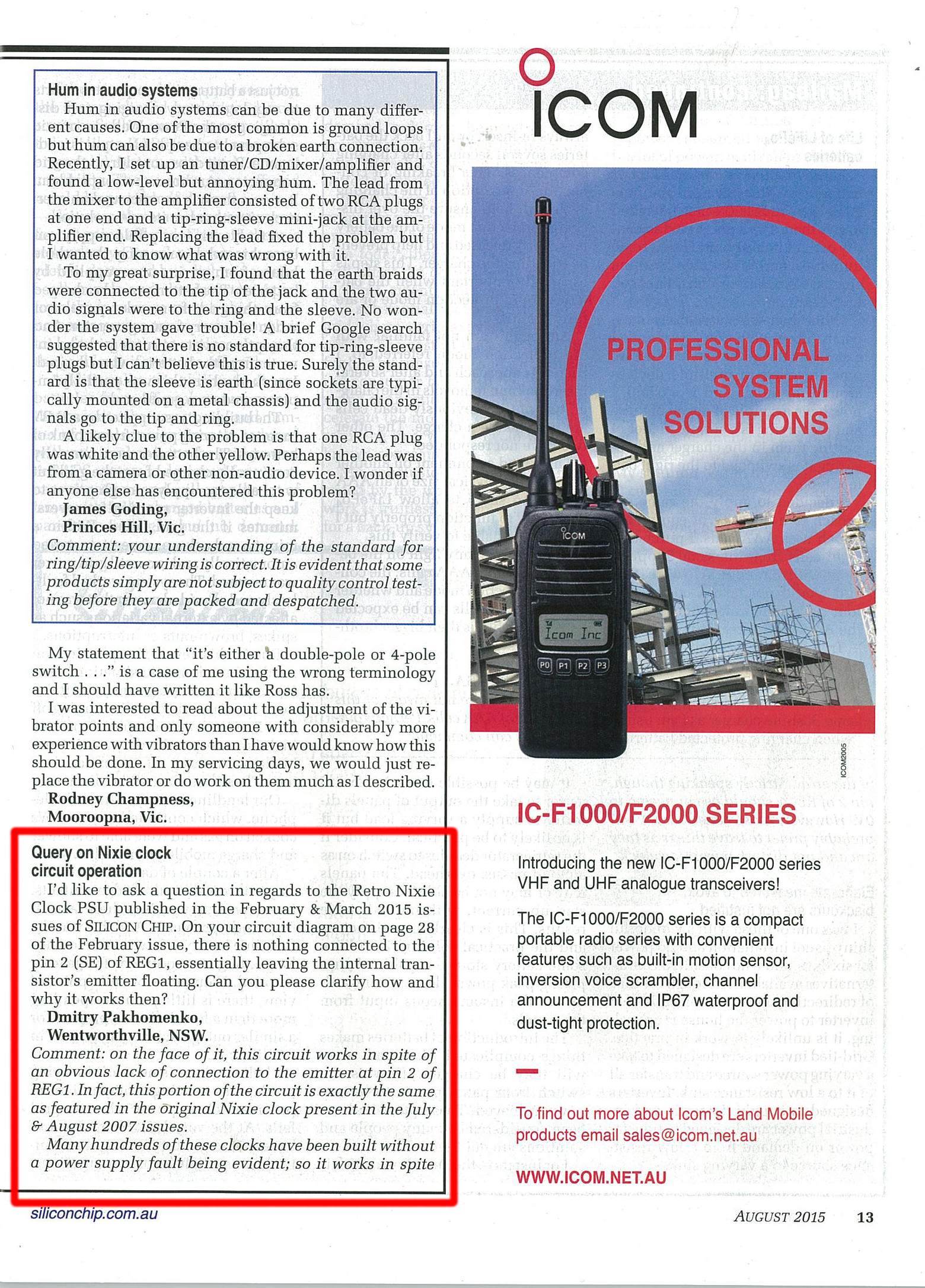 Silicon Chip Magazine – Editor’s response 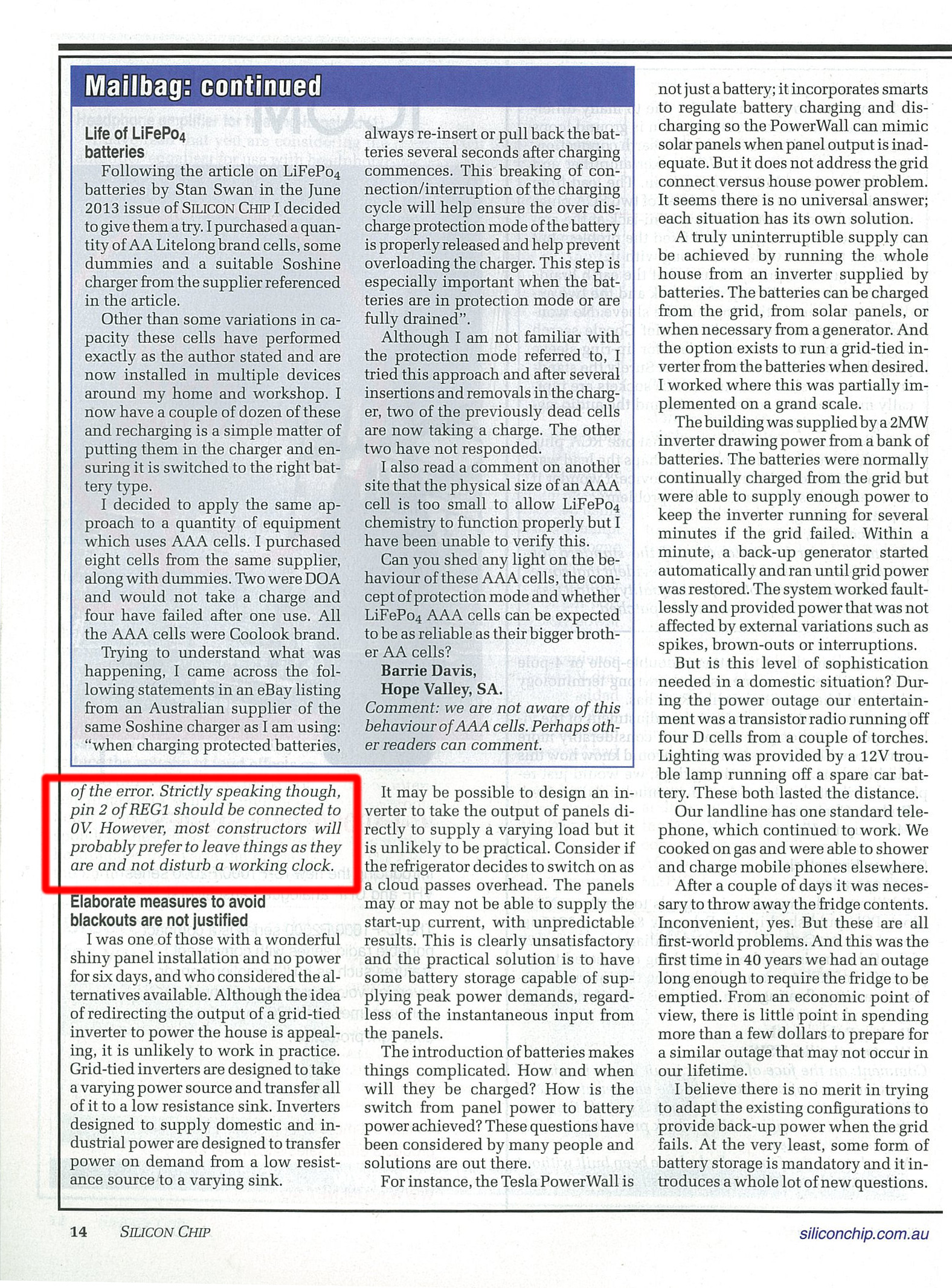 Silicon Chip Magazine – Editor’s response continuation Recently, after attending Ability-Maker-Meetup we were inspired by a group of friendly and openminded people with vision, passion, creativity and tremendous variety of skillsets. The people who share the same goal – to help those in need and with limited mobility by making openhardware things making hard lives of disabled people a bit easier and brighter. And by having design files free and open to anybody it would significantly reduce the final price of a product, increase its flexibility and make it possible to integrate with more platforms and other projects. It would also help to bring back to Earth people who totally lost sense of reality, people who sell primitive things for absolutely ridiculous prices like these. No wonder that we soon found ourselves being inadvertently involved into one of the projects. On a surface the project sounded really simple – design a wireless button with tactile sensation for scanning software to communicate to a tablet PC for just under $40. However, this quickly led to conflicting requirements. First of all, a wireless interface needs battery and the last thing you want is to put a wireless button on charge every night. Especially if you are not as mobile as an average person. Which means that we need an ultralow power consumption and it really leaves us with two options: low energy Bluetooth (aka Bluetooth 4, aka BLE) and Zigbee. Most mobile devices don’t have Zigbee radios and it is rather exotic piece of hardware. Yes, there are Zigbee dongles in micro SD card form factor so potentially it is possible to make, for instance, a mobile device Zigbee enabled at the cost of not having external flash memory. Also, this solution would require specific drivers to support Zigbee connectivity. On the other hand, most mobile platforms have inbuilt Bluetooth radios. Not all of them are compatible with BLE standard, however, and it is BLE only that can give us truly low power consumption allowing to give enough juice to a button for months if not a year or two and even a coin battery would have enough capacity for this. Another thing to consider is development effort on a mobile platform side, to be more specific, absence of such. Otherwise the development time for one driver would be multiplied by the number of mobile platforms that ought to be supported. In the world of USB the most obvious choice would be HID. There are also implementations of HID over Bluetooth and if we choose this one there won’t be need for any custom made driver at all. It is worth mentioning, however, that not all mobile platforms with BLE stack have HID support – this problem could be solved by using another (even user-specific) Bluetooth 4 profile and implementing custom driver on a mobile platform. But how to deal with mobile platforms that don’t support Bluetooth 4? Currently there are solutions on the market which are both Bluetooth 2 and Bluetooth 4 compatible but such a compatibility comes at a price: they are more expensive and more power hungry as in essence they have to accommodate two radios so by using them we would shoot ourselves in a foot again with need to recharge/replace batteries every so often. So our choice would be to have a pure Bluetooth 4 button only and design and distribute separately a ‘Bluetooth-4-to-whatever’ translator that is powered by a wall adapter. This translator, however, would be out of scope of this article. We also need to keep in mind that instead of using specialised chips we actually need an FCC certified module with fixed antenna. That way we can safely avoid intricacies of RF designing (which is more like black magic than actual designing) and possible customers’ accusations like ‘your device can cause harm to a live tissue by its electromagnetic radiation’. Summarising the requirements and ‘nice to have’ features, there is the list of criteria for a potential BLE module that we will be going to look for:
As a result of our search the best candidate matching our requirement would be BLE112-A-V1 module for the retail price of $15.66 from Digikey as it is shown on the picture below: 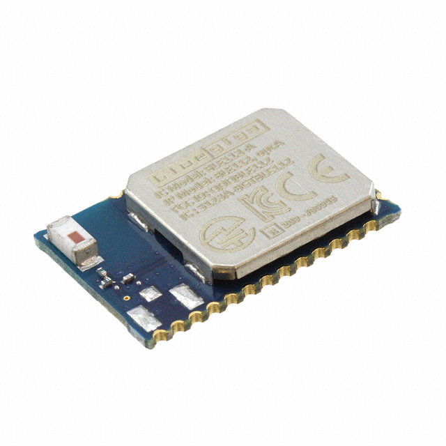 BLE112-A-V1 Module At a first glance the module looks amazing: a 8051 processor as a core which makes it possible to write conventional C code and upload it to the module, three (!) ways of firmware upload – either over USB interface, OTA (over the air) or by means of CC-Debugger (oh no, the chip is made by Texas Instruments, a notorious cheater with CC2430 Zigbee chip, overpriced development environment for it, buggy and unstable Zigbee stack without access to source code and cowardly abandoned support). However, after a closer look it is seen that there is no way to write in C when not using an external host processor and the code has to be written is a BASIC-like compilable script invented by Bluegiga. As for the firmware uploads, once USB is enabled it uses so much power that it defeats the whole purpose of low energy Bluetooth and OTA works only if certain conditions are met so it really leaves us with the only way – CC-debugger (which would cost us some additional money). Apart from these inconveniences everything else looks quite reasonable so we are going to use the module as a cornerstone for our project. The fist revision of circuit diagram is given below. The module and capacitors 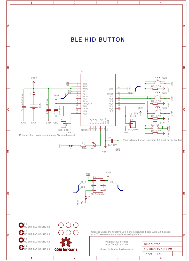 Blueutton Circuit Diagram Rev.1.0 A PCB layout is done on 2 layer 50x50mm blanks to take advantage of budget PCB manufacturing service by ITeadStudio. On the top side the buttons are the most extending mechanical parts to accommodate a big round plastic lid on top covering all four buttons. The bulky components are residing on the bottom side. Both top and bottom sides are filled with copper polygons connected to ground with cut-off window near module’s antenna area as per datasheet layout guidance. The two ground plains are stitched with vias across the cut-off’s perimeter to minimise noise and electromagnetic emission as much as possible. Our initial intention was to squeeze everything into Keyfob case but after thorough consideration the idea was rejected because of the really small rubber button which would be difficult to press so the decision was to make a 3D printed case specifically designed for our PCB. 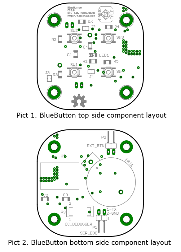 BlueButton Component Layout Rev 1.0 A 3D model of the PCB is provided below. 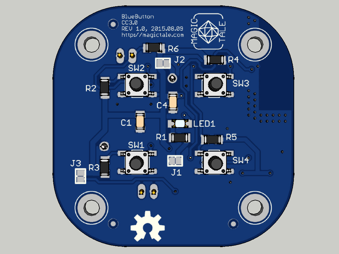 BlueButton PCBA 3DModel Top View 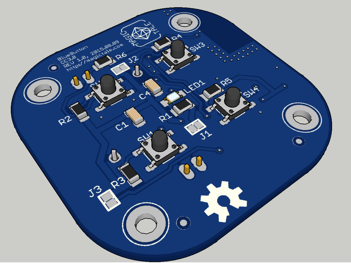 BlueButton PCBA 3D Model Top Iso View 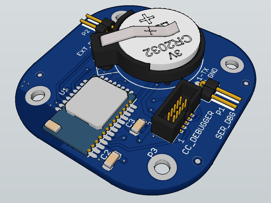 BlueButton PCBA 3D Model Bottom Iso View Upon arrival of the manufactured PCBs we will be assembling the first prototype and testing our custom made scripts. Also we will be designing a simple enclosure model which then most probably will be 3D printed. All this will be posted in the next article. Downloads:1. BlueButton Gerber files Rev1.0 2. BlueButton Eagle files Rev1.0 3. BlueButton PCBA SketchUp 3D Model Rev1.0 It is time to test our revisited VFD PSU in real life. We are going to build a quick prototype using a PCB from MVFD 16S7D Panel with minimum components loaded. All we need to solder is a VFD controller IC2 (instead of HT16515 we are going to use PT6315 as they are pin-to-pin compatible), a 82k resistor R14 to keep controller’s oscillator running, a decoupling 100n capacitor C11 and CTRL connector along with VFD glass VFD1. The PCB is then connected with the PSU to provide filament (~2.5ADC), high voltage (-24VDC) and logic voltage supply (+5VDC) as shown on the picture below.  VFD_PSU_EXP01 VFD Driver Soldered To drive the VFD controller our specifically designed Arduino compatible VFD Serial Backpack is used. The backpack is programmed with a slightly modified Magictale VFD Demo lib published in VFD driver demo article. The backpack is simply attached to the VFD panel, it gets power from it and at the same time communicates with PT6315.  VFD_PSU_EXP01 Backpack Attached The prototype works smoothly, in our experiment it jumpstarted immediately without any troubleshooting. The brightness of the VFD is much better than the original MVFD 16S7D panel. Also there is no brightness gradient, thanks to the pulse filament drive.  VFD_PSU_EXP01 With Serial Backpack However, nothing can be perfect. This solution exhibits a ghosting effect when some segments are faintly glowing while they actually must be completely dark as it is shown on the picture below. The reason for this is absence of cut-off voltage which we hopefully can solve by adjusting some components of the PSU but this will be our next exercise. 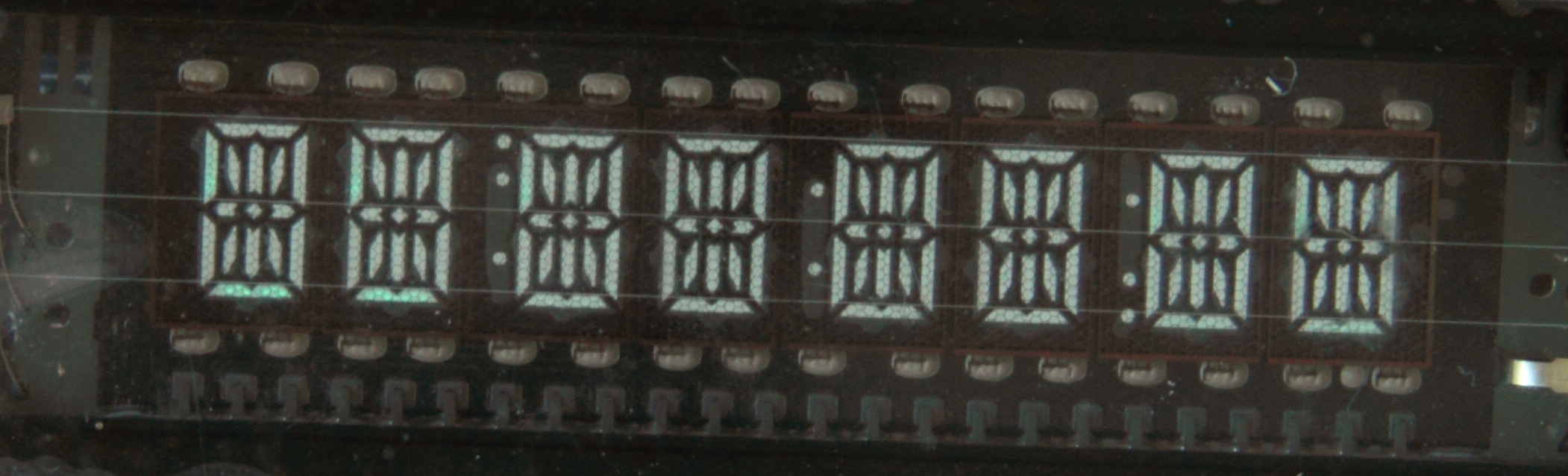 VFD_PSU_EXP01 Ghost Effect Despite of a couple of annoying issues such as ghosting effect and a bit excessive current consumption of the whole prototype (250mA) we managed to prove that the new PSU is generally functional and has some improvements over the old design. And most importantly, it is very cheap and doesn’t have fancy chips which could potentially become obsolete in nearest future without any hope to be replaced with something similar. UPDATE: R9 = 2.1K, R10 = 9.1K to cancel ghosting effect. We are continuing our experiments with an alternative VFD power supply which we started some time ago. The high voltage part remains pretty much unchanged for now – it is an inverting regulator based on inexpensive chip MC34063. Excessive current consumption (60-70mA) in idling mode is still an issue but we are not going to address it today and the circuit diagram of HV part is in essence what we had during the previous experiment: 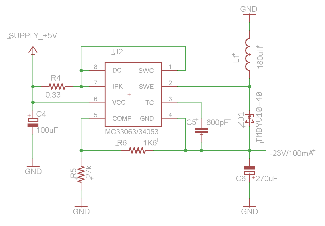 MC3463 Inverting Regulator The second part, a filament driver, is based on a… LM4871 audio amplifier. We have been inspired by the idea described in great detail in The VFD Stuff article but what we didn’t like in the original design was a requirement for 12VDC (and we wanted a solution capable of working off 5VDC). Also, LM1877 is an old chip, so old that it doesn’t have a shutdown pin. Learnt on our previous mistakes we didn’t want to use something which could become obsolete at any point in time. Having a few things in question and before rushing and finalising our PSU design we also wanted to build a prototype to make sure that it would going to fly. So the following simplified circuit diagram was used to test its pros and cons: 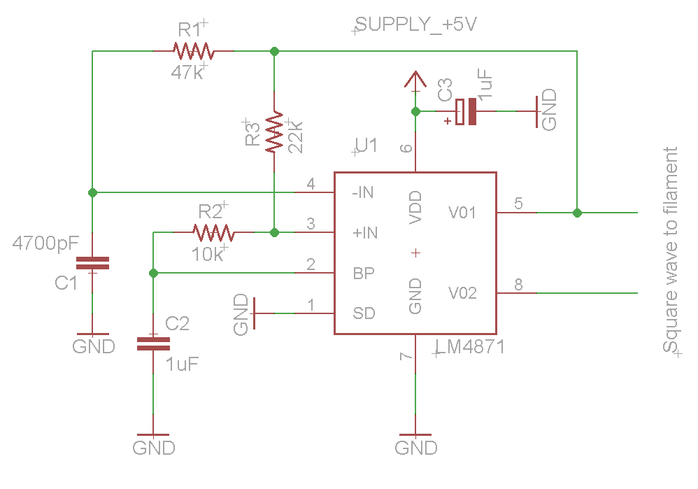 LM4871 Square Wave Generator A SOIC-to-DIP 8 pin adapter, bunch of wires and jelly beans have been used for a proof of concept, no PCB. To our surprise, the circuit was not demonstrating stable results, the generated square wave had some parasitic spikes the amount and magnitude of which varied greatly over time and we couldn’t understand the reason. 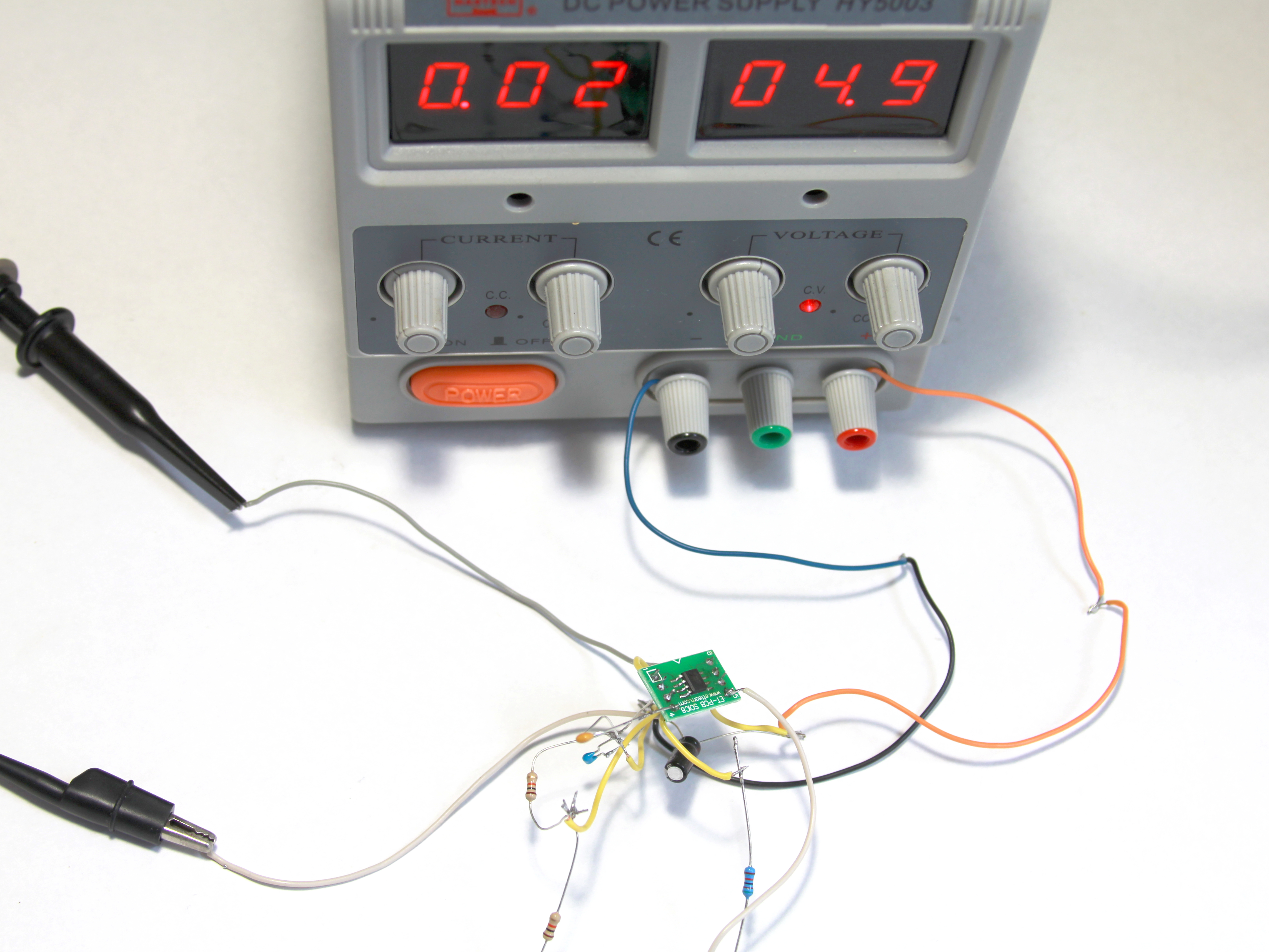 VFD_PSU_EXP01 Test Without PCB The two pictures below shows two spikes at the beginning of a square pulse and this not a bad case as we witnessed much, much worse. Eventually, after numerous on/off switch cycles and attempts to comprehend the nature of the noise we ended up with entangled wires killing the amplifier in the end as a result. 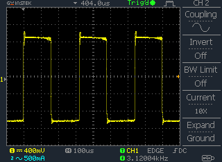 Square Wave Parasitic Spikes without PCB 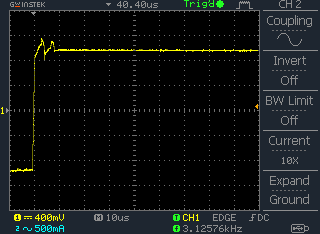 Square Wave Parasitic Spikes without PCB After the failure we decided not to repeat same mistakes and build a prototype on a proper PCB thanks to ITead Studio, it is very cheap now. The two parts (HV and filament driver) have been merged into a single circuit diagram as shown below. We deliberately made some room for more things to try and adjust: voltage dumping resistors R7, R8 (which needs to be later replaced with something more elegant), transistor Q1 to play with current consumption in idling mode for HV part and the trick of offsetting filament AC voltage down to -20…-24V (R8, R10, C7, C8). 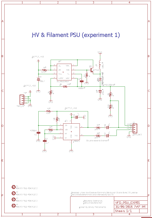 VFD_PSU_EXP01 Circuit Diagram The board was easily routed and fitted on a standard blank of 50x50mm, some real estate has been even reserved for prototyping area. All components reside on a top layer as shown below: 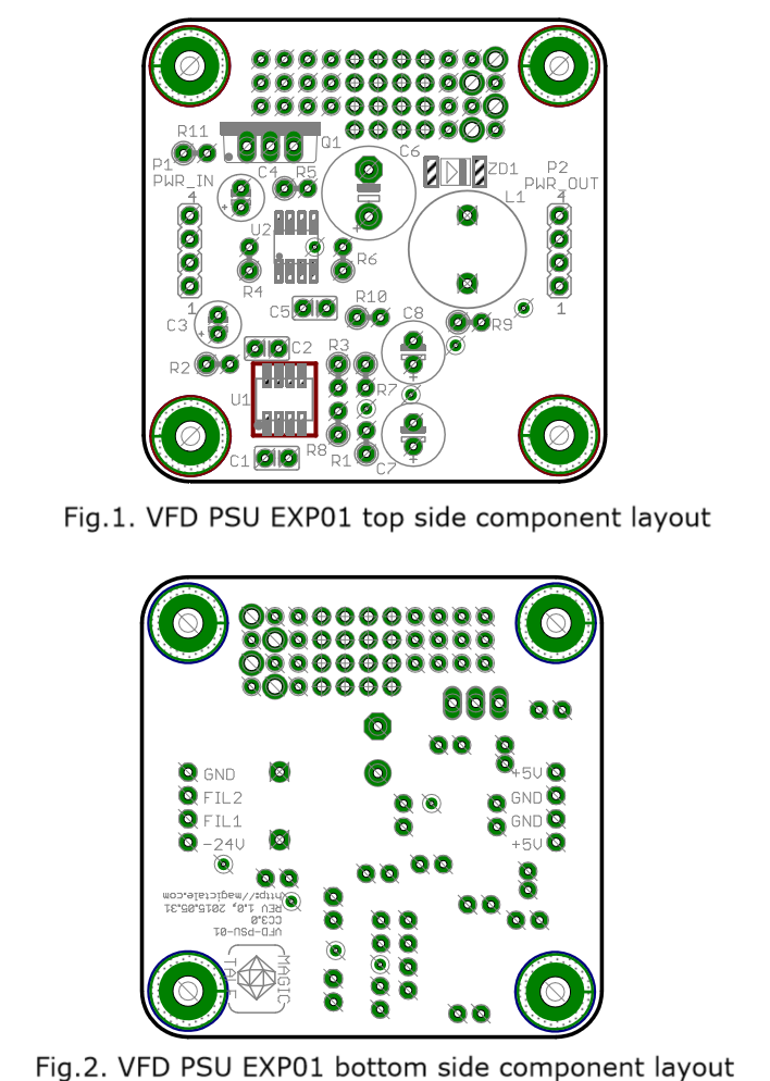 VFD_PSU_EXP01 Compoment Layout Then a 3D model of PCBA was designed to make sure that there was no interferences between components and nothing was overlooked: 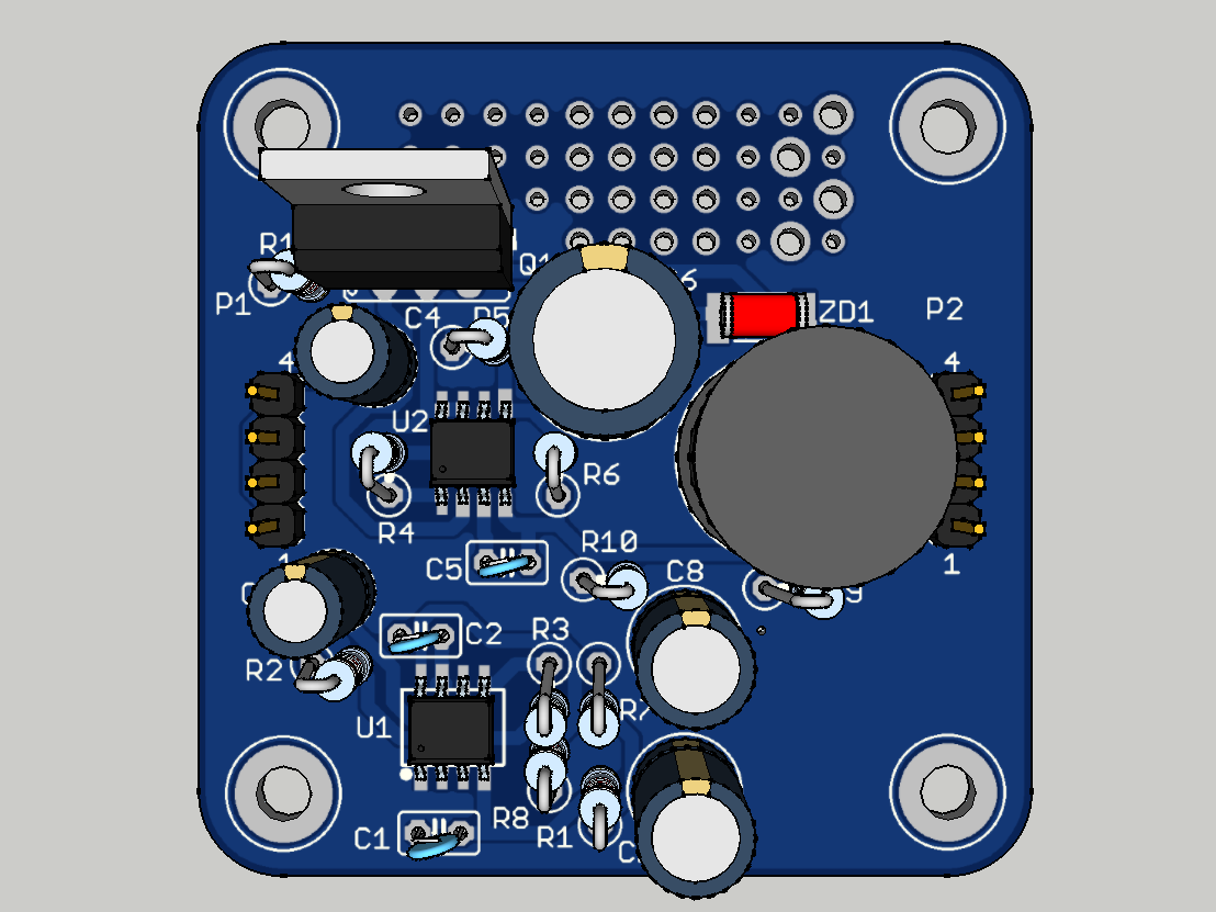 VFD_PSU_EXP01 PCBA 3DModel Top View 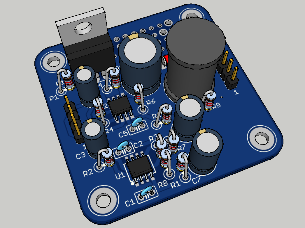 VFD_PSU_EXP01 PCBA 3DModel Top ISO View 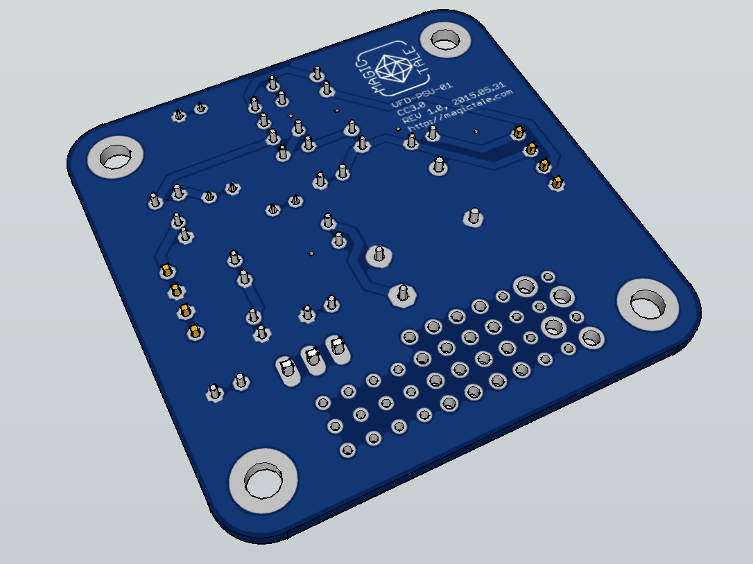 VFD_PSU_EXP01 PCBA 3DModel Bottom ISO View The manufactured PCBs arrived exactly in two weeks, no surprises here:  VFD_PSU_EXP01 PCBs Manufactured First PCBA has been loaded with components, as per original schematics Q1 and R11 are not loaded instead Q1 Base and Emitter are connected with a wire, R10 is not loaded and R10 is replaced with a wire. 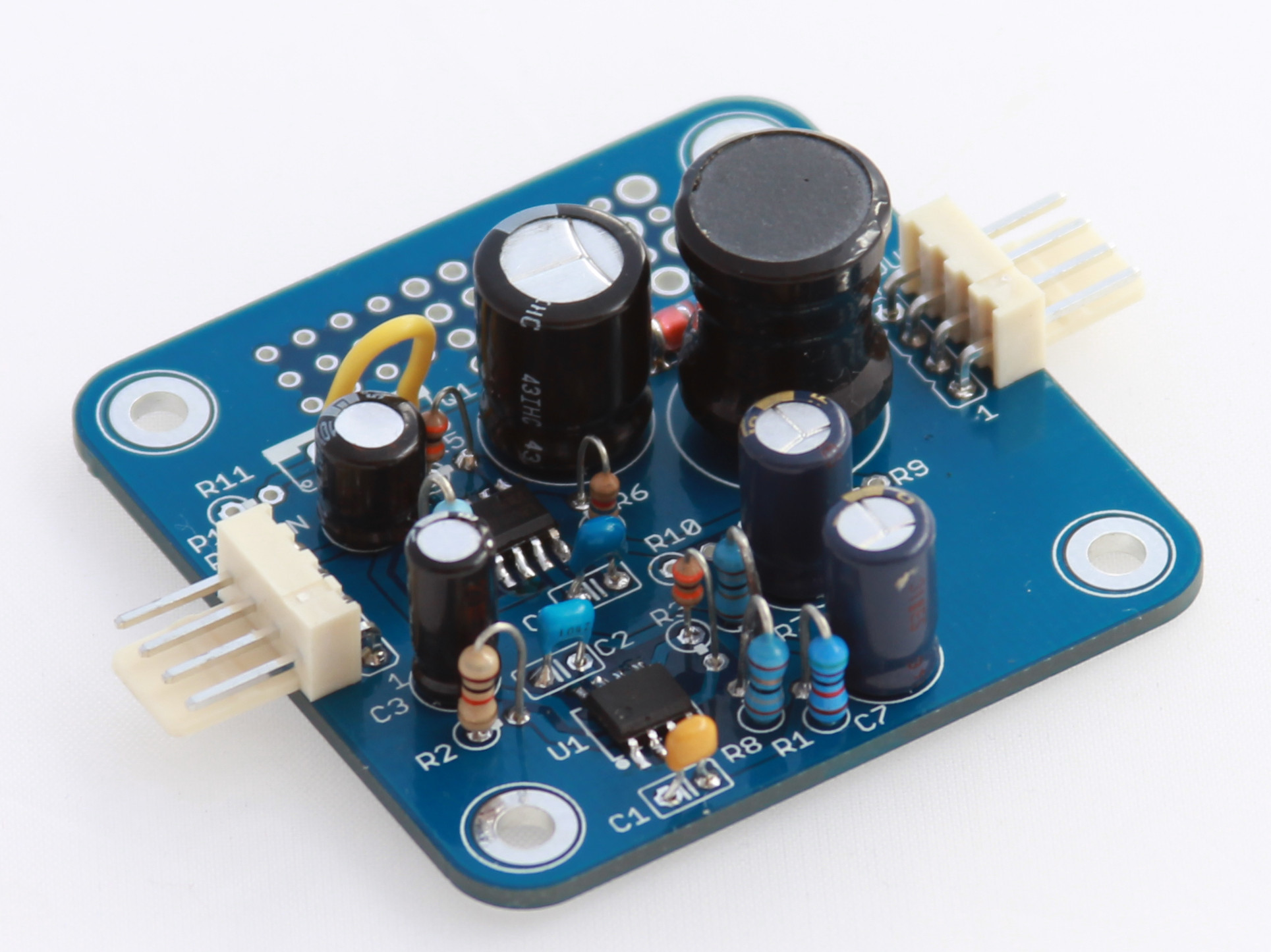 VFD_PSU_EXP01 PCBA Assembled Generated square wave is much more cleaner now, all parasitic spikes disappeared:  Square Wave No Parasitic Spike On PCB 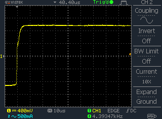 Square Wave No Parasitic Spike On PCB And the most important step is actual connection of a VFD. As we don’t have any controller at the moment we can simply apply filament voltage and pull one grid and one segment to ground (not to -24V, it is actually filament voltage which oscillates about -24V). The picture below shows that our prototype works even though is consumes a bit excessive current – 230 mA. Our goal would be to bring it down to 150 mA in the next exercise. 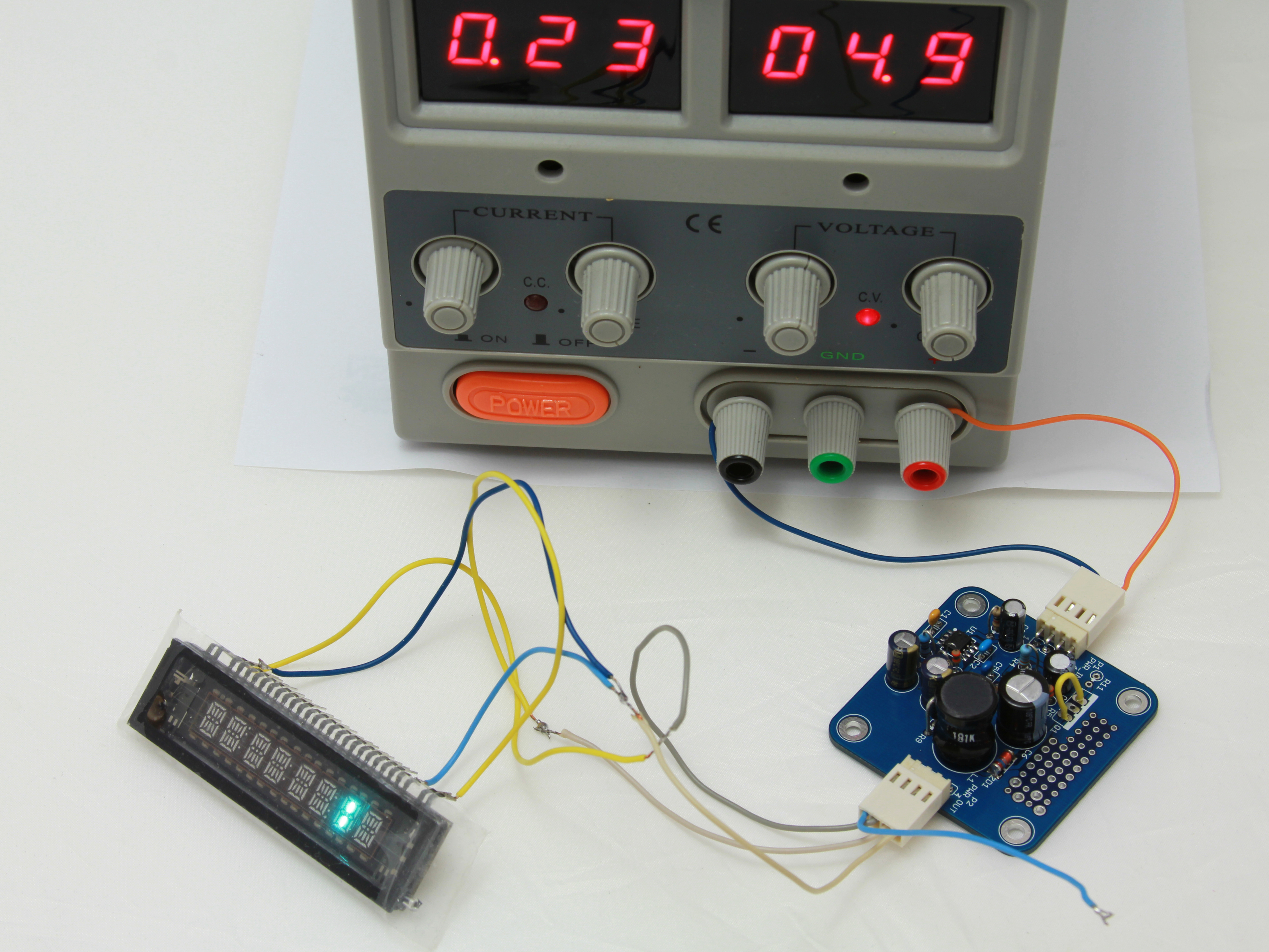 VFD_PSU_EXP01 In Action Downloads:1. VFD_PSU_EXP01 Gerber files Rev1.0 2. VFD_PSU_EXP01 Eagle files Rev1.0 3. VFD_PSU_EXP01 PCBA SketchUp 3D Model Rev1.0 Let’s make something more complex using Luminardo, a Bluetooth dongle, a OBDII translator ELM327 and a 128×64 pixels graphical monochrome OLED display SSD1306. The plan would be to utilise USB host functionality to communicate to ELM327 via SPP interface and represent such parameters as engine RPM, vehicle speed, battery voltage, remaining fuel on a display. In a way it will be like the well known OBDuino, however, we are going to take full advantage of a graphical display and in our case we are going to have a wireless communication interface. For simplicity sake we won’t implement trip computer to calculate distance traveled, fuel consumption per 100 km or tank distance, instead, we will be focusing on user interface and modular firmware architecture which would allow to integrate additional functionality later and with minimum development effort. The information displayed on a display in mostly numeric, some of them more significant, some of them less, so most probably we will need to have several font sizes (or fonts). We strongly believe that it this application numeric data would be looked more professional if seven segment font is used. And if so, we would need to add more seven segment fonts as we have only 32×50 Next step is to prepare icons, the plan would be to display a number next to icon so that it would be intuitively clear and obvious what kind of information a number represents. For example, a battery icon for voltage readings, a fuel dispenser icon for tank level, a thermometer icon for temperature readings, well, you’ve got the idea. The will be two icons of the same type – one which fills the whole display for warnings in case of critical levels and one is of a regular size, 18 pixels maximum in height to roughly match with the small seven segment font. We would need the following icons: a car battery, a bluetooth, a fuel dispenser, a thermometer, a ‘car doors open’, a clock. The last two are ‘just in case’. All these icons will be defined in Let’s also specify the most important architectural considerations. First of all, we will be heavily relying on Bluetooth communication between our Luminardo board and ELM327 OBDII adapter. Therefore, we will have to indicate explicitly connection status and upon boot up don’t progress to any screen with numbers until the connection is successfully established. It would be also necessary to distinguish two different states of connection: successful pairing/connection with ELM327 and successful recognition of the OBDII protocol with ability to communicate to a vehicle. That way to will definitely detect situations when Luminardo can communicate to ELM327 but ELM327 can’t communicate to a vehicle. It would be also highly desirable to display additional information about ELM327 upon connection – for example, its firmware revision number. Next, we won’t be using delays in our code as it is very wasteful style of programming, especially for embedded devices with their limited computational power and battery power sources. Given that we have only single thread process (which is a limitation of most 8-bit microprocessor systems including Arduino) required delays between subsequent operations will be achieved by introduction states and counters, holding number of milliseconds passed since the previous operation. That way in the main loop we will be checking each counter whether it is time to progress to the next state, execute next operation and update counter with a new value or simply move on to check next counter. The code execution flow in this case will be non-blocking as this is exactly what we want. Some parameter values will be refreshed less frequent than others. For example, engine RPM and vehicle speed will be requested from the vehicle every time when display is refreshed whereas tank level, battery voltage and temperature values change much slower and therefore they need to be retrieved and updated on the screen less frequent. Given, that from our previous experiments with display we discovered that full frame refresh takes longer than the actual transfer of block of data from microcontroller to OLED, we will be updating only those areas on the screen which are changing. In other words, if we retrieved just new values for PRM and speed we will be updating only appropriate numbers on the screen and nothing else. With modularity and simplicity in mind, the sketch will be subdivided into several logical parts: the main part There are two things to be configured before your Luminardo board will be able to find and connect to your ELM327. It is ELM327 Bluetooth address and pin code. Note, that Bluetooth address is specified in reversed order as shown in the code below:
//40:22:11:00:69:58 ELM327 OBDII
uint8_t remote_addr[6] = {0x58, 0x69, 0x00, 0x11, 0x22, 0x40};
SPPi SerialBT(&Btd, "Luminardo", "1234", true, (uint8_t*)&remote_addr);
It is also possible to adjust warning thresholds, these are: battery low voltage level (in volts multiplied by 10) and tank level (percentage remain) as shown in the code below: #define BATTERY_VOLTAGE_WARN_THRESHOLD 110 //Multiplied by 10 #define TANK_LEVEL_WARN_THRESHOLD 30 //Percentage remain Luminardo was specifically designed with slim form factor in mind and more small but useful features if compare with Arduino boards. However, given that Luminardo is an Arduino clone, it is possible to build the same functionality using an Arduino board. The final result will be rather bulky but nevertheless, it is still very much possible. The final source code is freely available below. Downloads:1. Luminardo_OBDII_BT_SSD1306_2015_04_29.zip Luminardo OBDII sketch with customised SSD1306 OLED library; 2. USB_Host_Shield_2_SPP_Client_Support_2015_05_05.zip Customised USB Host 2.0 library with SPP client support; 3. Github repository with Luminardo core for Arduino environment; As the headlining in our Toyota Camry 1998 was deteriorating we decided to do something about it. But instead of rushing to the nearest auto upholstery/motor trimmers we tempted to do it ourselves. What does it have to do with electronics, an attentive reader would ask. Well, if we were going to deal with roof repair anyway then it would be a great opportunity to fit a dashcamera at the same time hiding all the wiring behind the roof and/or plastic panels. Knowing that it would make us spent quite some time we didn’t even suspect what we were getting ourselves into but nevertheless we still think that it was worth the effort. A little bit of theory. Sagging roof is usually caused by time and temperature which disintegrate fabric’s foam layer. As a result, fabric is slowly getting loose. The more fabric gets loose, the faster the process goes. What makes it particularly disappointing, there is no quick solution. It is absolutely pointless to inject some glue or adhesive between foam panel and fabric as the panel is covered with disintegrated stuff and has to be thoroughly cleaned first. Before doing anything with the old fabric we need to get some materials and tools. For a passenger car like our Toyota Camry we would need 2 meters of new gray fabric and adhesive. Not saying that it was the cheapest option but this was what we ended up with after a little bit of shopping around in Sydney. As per usual, here is a our comparison between ‘doing yourself’ and ‘asking someone to do it for you’:
No doubts, each option has its own pros and cons. Letting professional to do the job is obviously faster but more expensive. We wouldn’t gain any new skills too. When doing ourselves, it is more time consuming, challenging, requires some tools but cheaper, more fun and more experience in the end. It also allows us to deviate from boring standard approach and try to do something else – for example, install video recording system. And finally, when doing ourselves we can control the quality of our work and as a result, may have even better outcome, however, doing something for the first time usually means that inevitably there will be mistakes. In this post will be try to highlight typical pitfalls of this process and help others to avoid our misjudgments and miscalculations. First step is to dismantle foam panel with old fabric altogether. It requires removal of car’s interior elements including plastic panels running along the windows. If possible, do this with someone’s help, it is very difficult to remove the panel without breaking it with just one pair of hands – this is what happened to us, without knowing in advance we broke the foam in many ways. Also, when removing any plastic part, it is worth remembering that if we are applying too much force then it is a good indication that we are doing something wrong – stop, have some rest and examine the part one more time to understand better how it is fitted and what holds it in place. 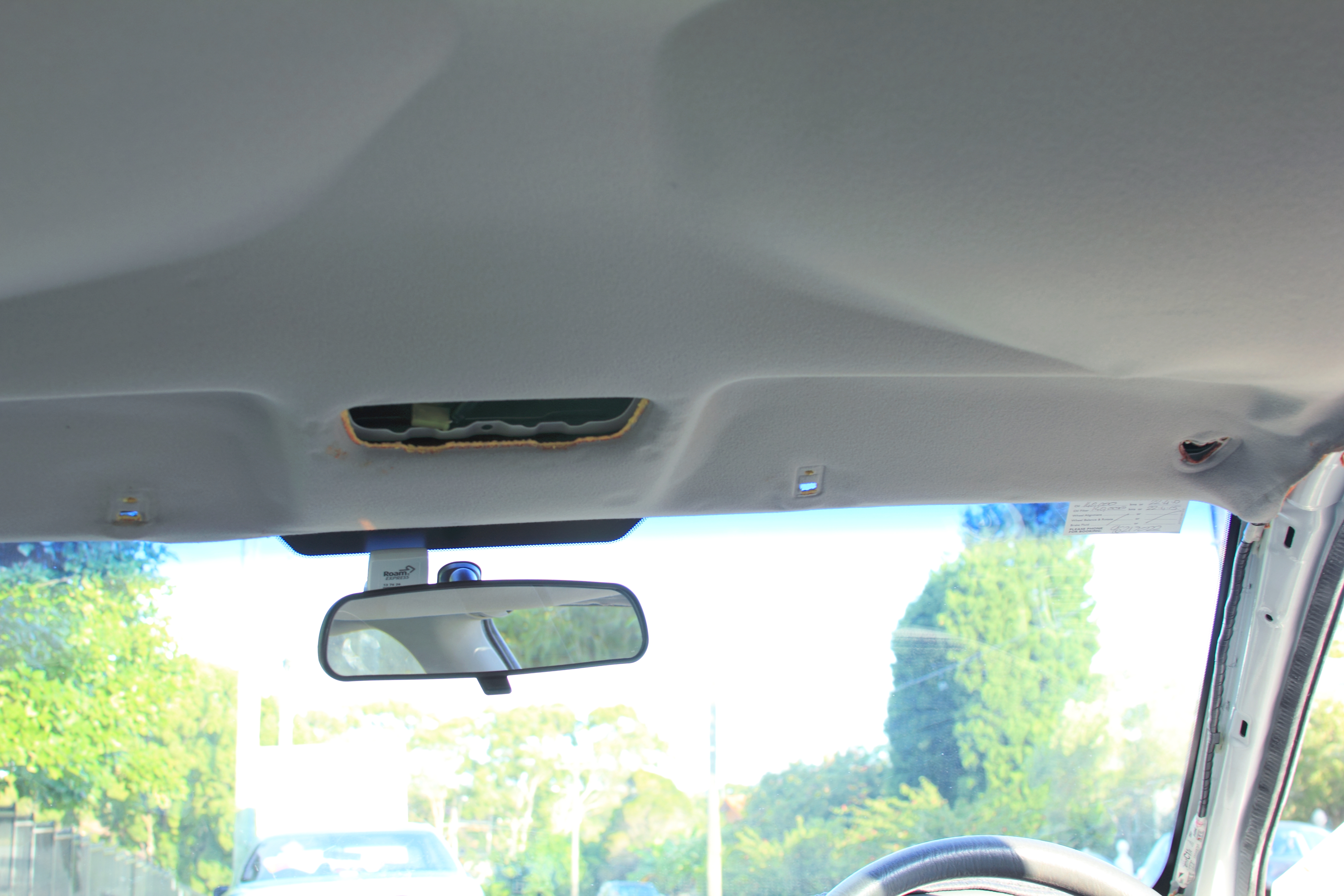 Sagging Roof Bring the foam panel to a dry place (preferable outdoors as we will be using toxic substance during our work). Get rid of the old fabric. 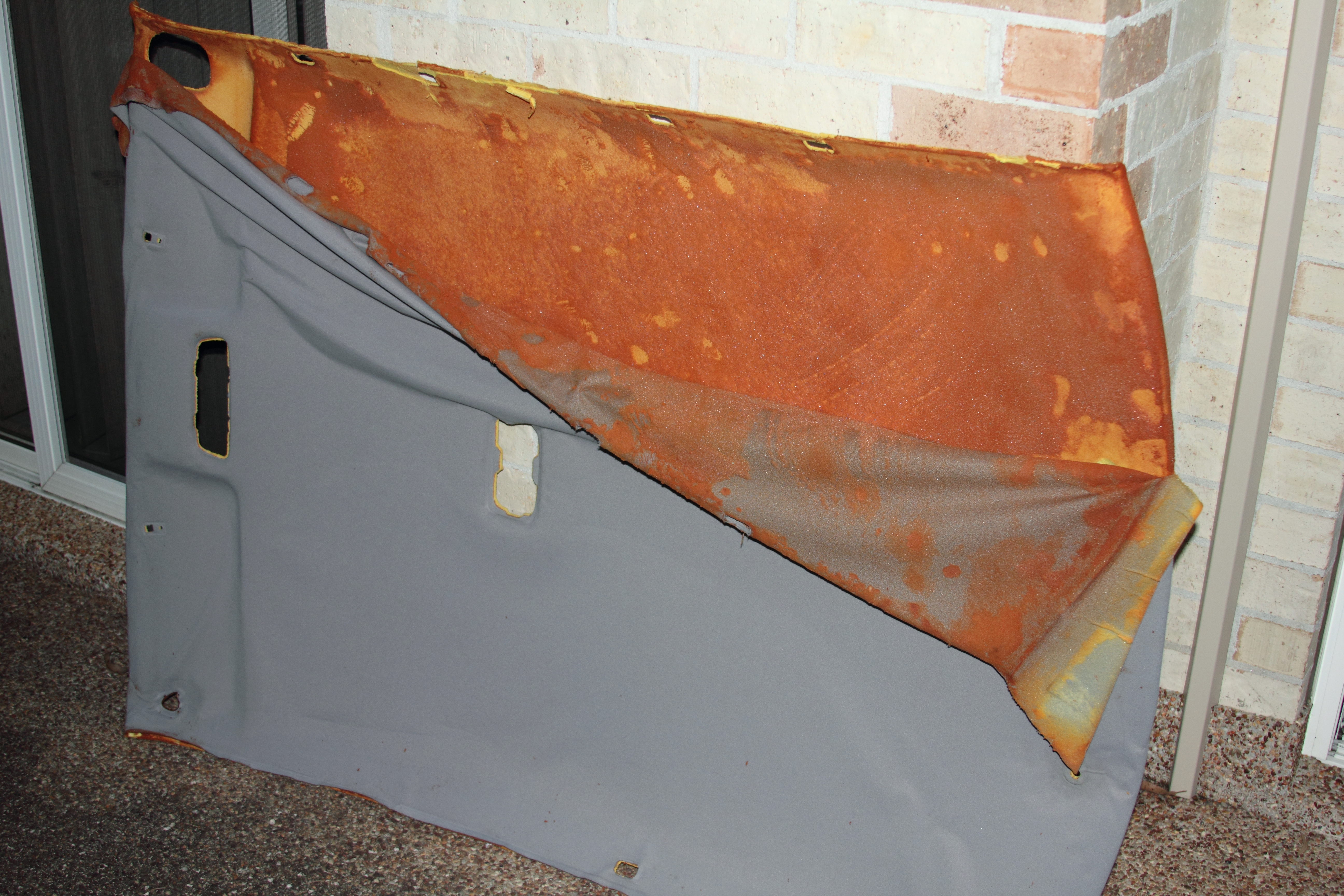 Foam Panel With Old Fabric Carefully clean the foam panel of the spongy layer which used to be a foam layer of the fabric. Without doing this all subsequent activities would be absolutely useless as adhesive wouldn’t hold. 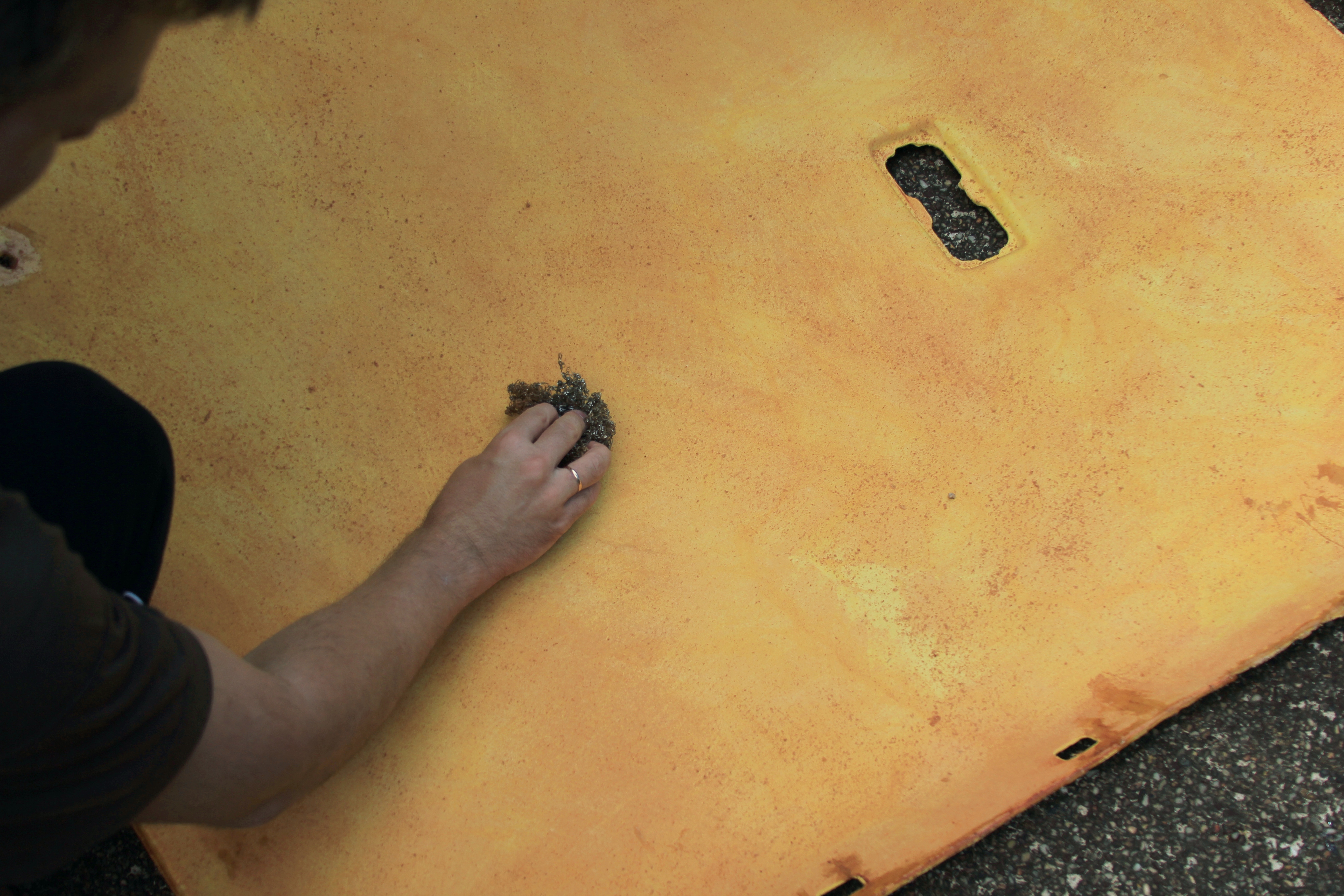 Toyota Camry 1998 Cleaning Foam Panel Restore the structure of broken foam panel (if it is broken as it was in our case). We used a two-component epoxy that cost about 2 dollars per pack. Keep in mind that epoxy is very toxic when in liquid state, take all the precautions as directed on epoxy’s label. 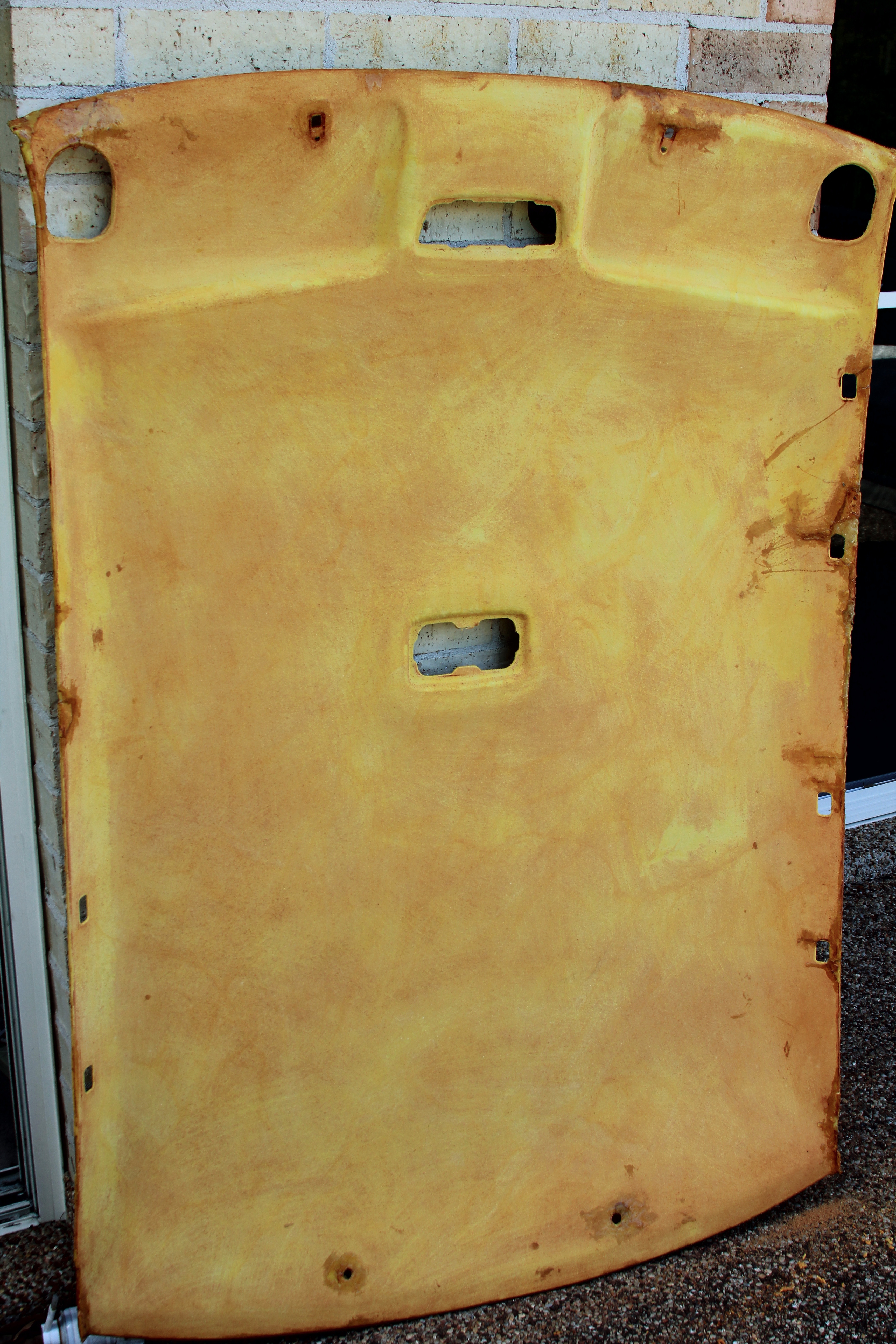 Toyota Camry 1998 Foam Panel_Cleaned And Restored Prepare new fabric and adhesive. Make sure that foam panel’s surface is clean as even small imperfections will be visible later through new fabric. Get ready the adhesive. Make sure there is no rain coming if you do it outdoors. 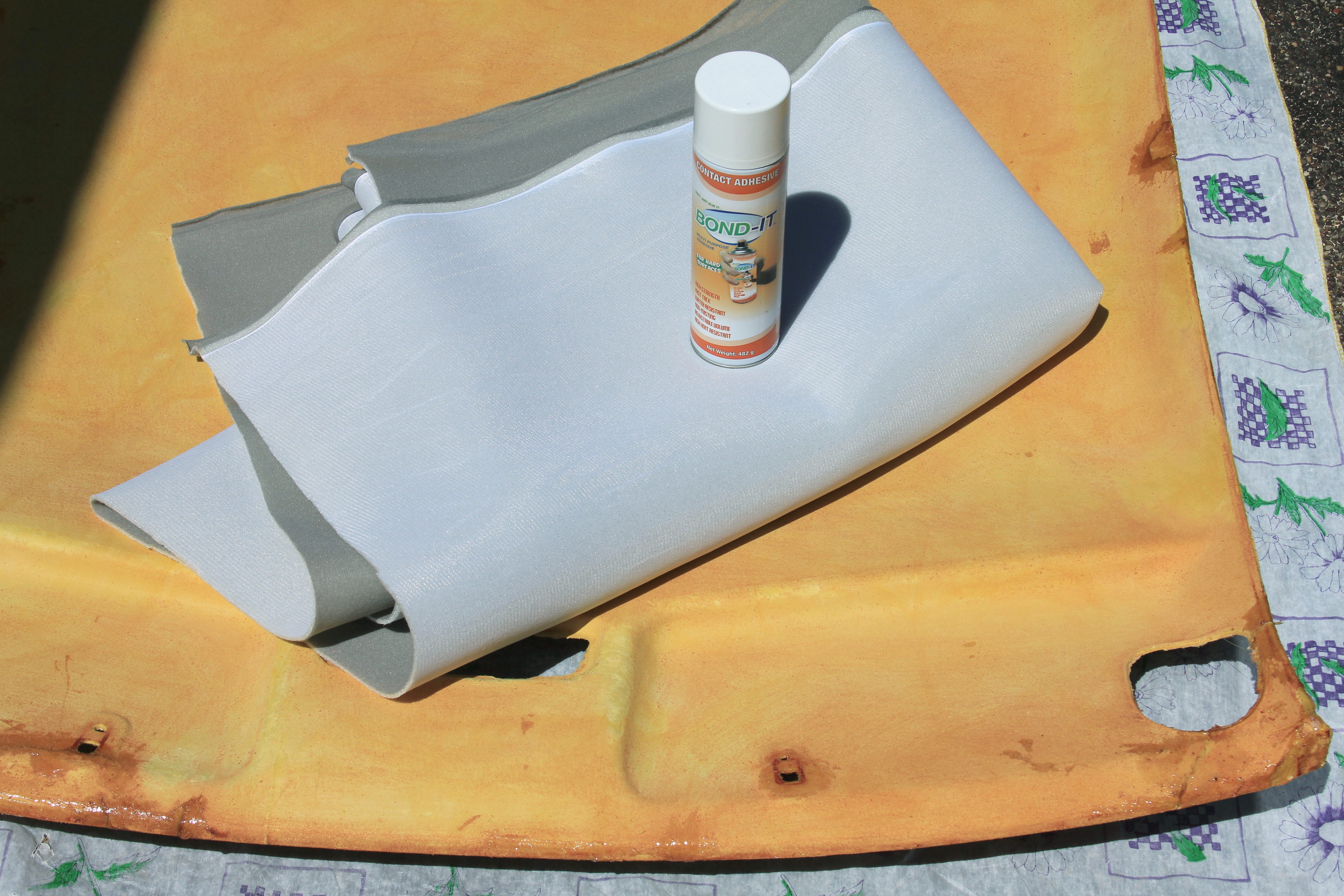 Toyota Camry 1998 Ready To Glue New Fabric Before applying adhesive do the final try on to avoid unpleasant surprises.  Toyota Camry 1998 Fabric Final Try On Start from the most difficult surface (usually it is the front one). Apply adhesive to the first quarter of the foam panel and to fabric, carefully glue and move on to the next quarter. At all cost avoid overlapping of the fabric with itself after adhesive is applied – it is very difficult to fix such issues. When done with gluing trim the excess of the fabric and let it dry for a few hours until the drying glue doesn’t smell anymore. 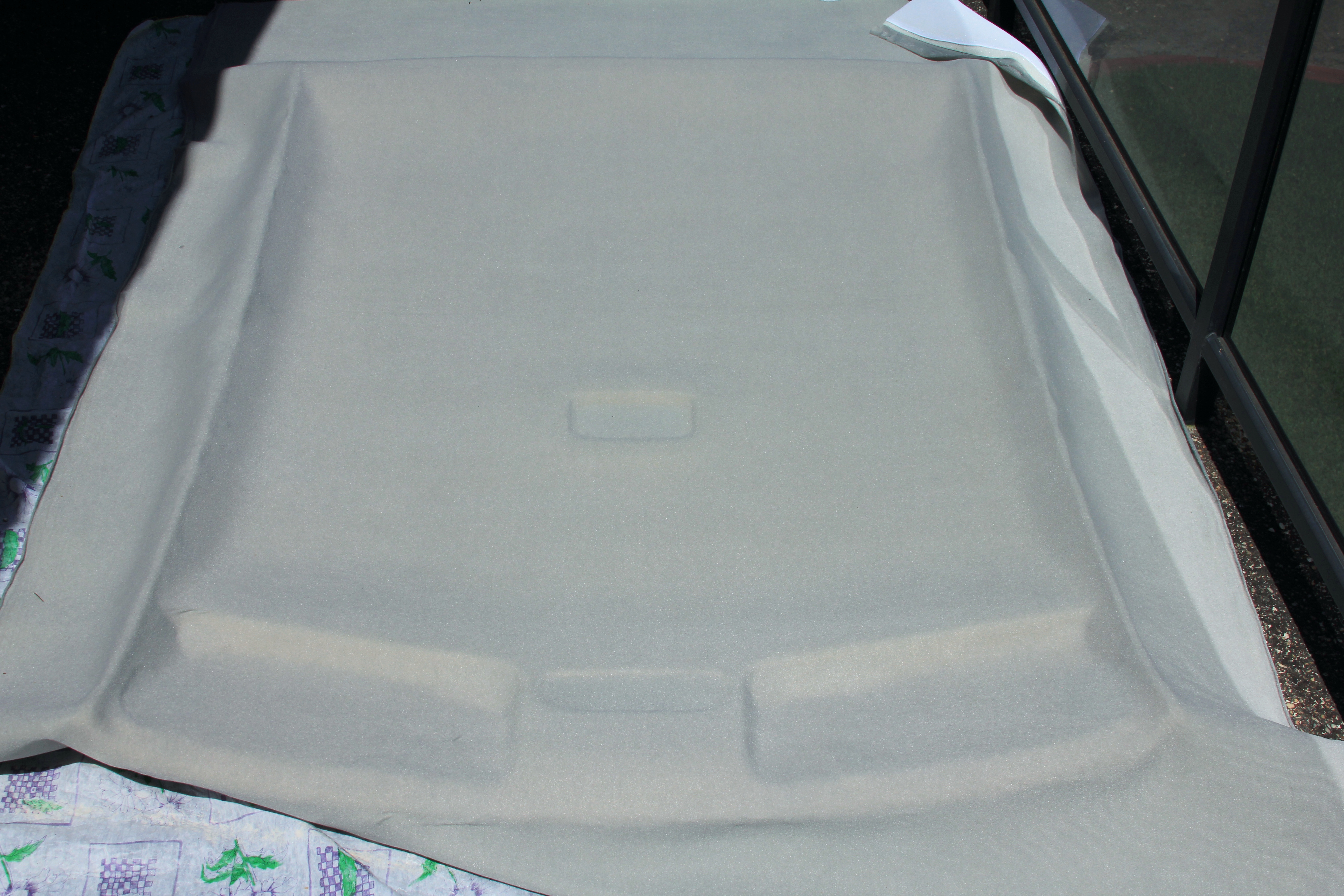 Toyota Camry 1998 Fabric Glued Before putting the panel back decide how you are going to install video cameras and how to hide wiring. We picked two channel Blackvue, one of the best video recorders currently on the market. It has two, front and rear cameras and the rear one is supposed to be connected with the front one via a coaxial cable. It would be reasonable to hide the cable behind the foam panel. Again, it would be highly desirable to do this part of job with more than just one pair of hands. This step is even more critical than panel removal – we can’t afford to make even one crack when installing the panel back. When the panel is finally back in its place adjust its location by installing grab-handles. 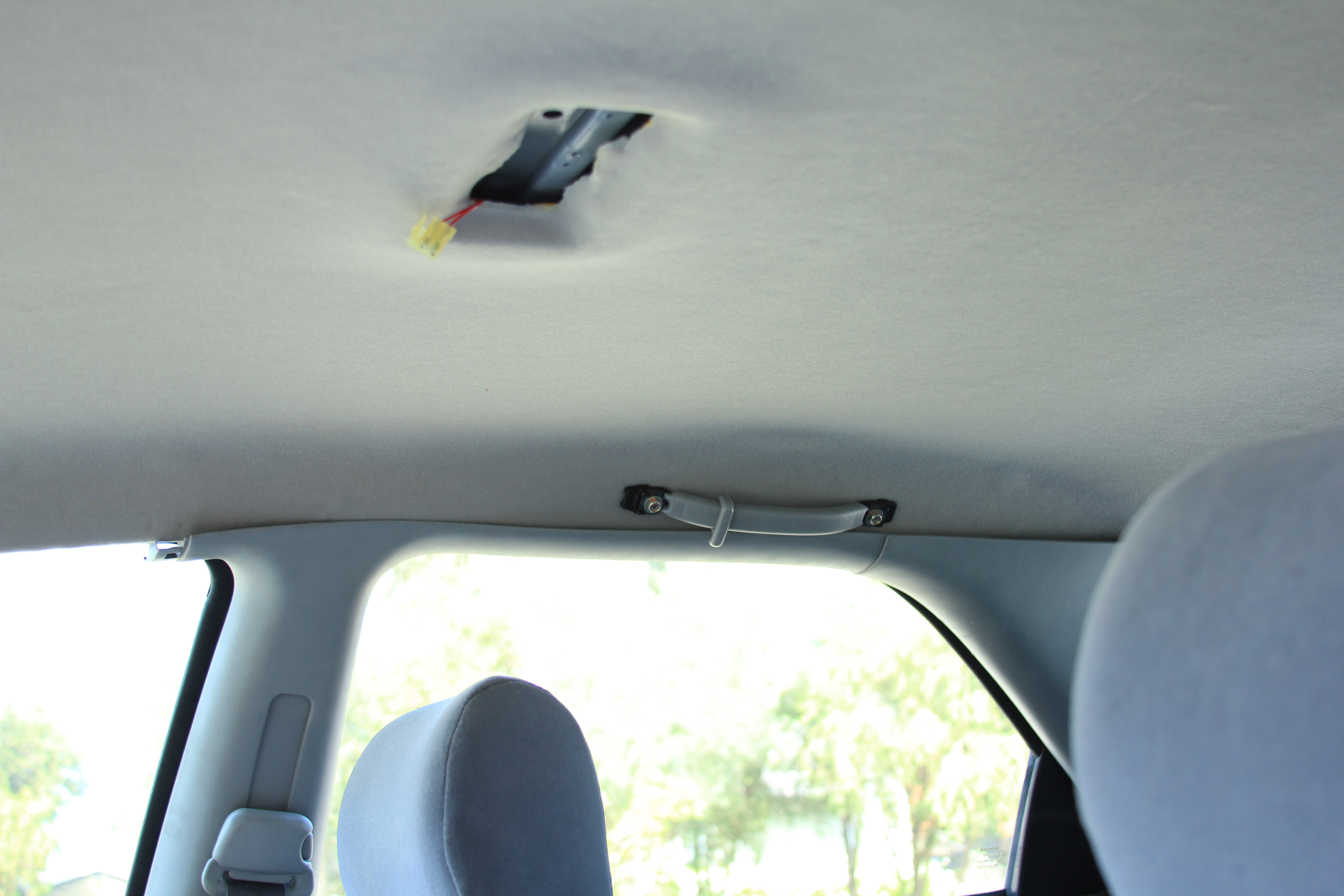 Plastic Panels Not Secured Yet Next step is preparation for sun visors fitment. 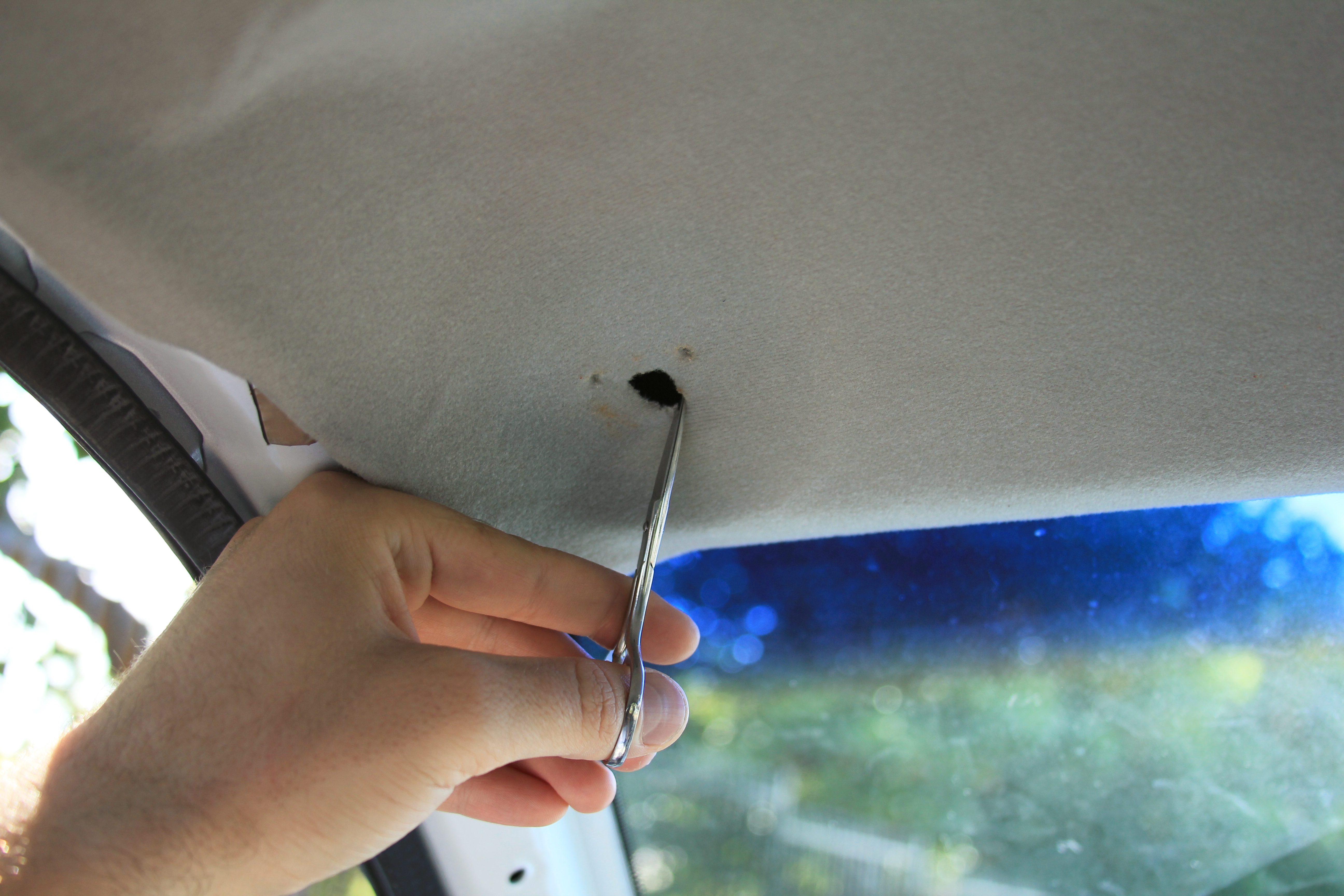 Preparation For Sun Visors Fitment … and then comes the actual visor fitment. 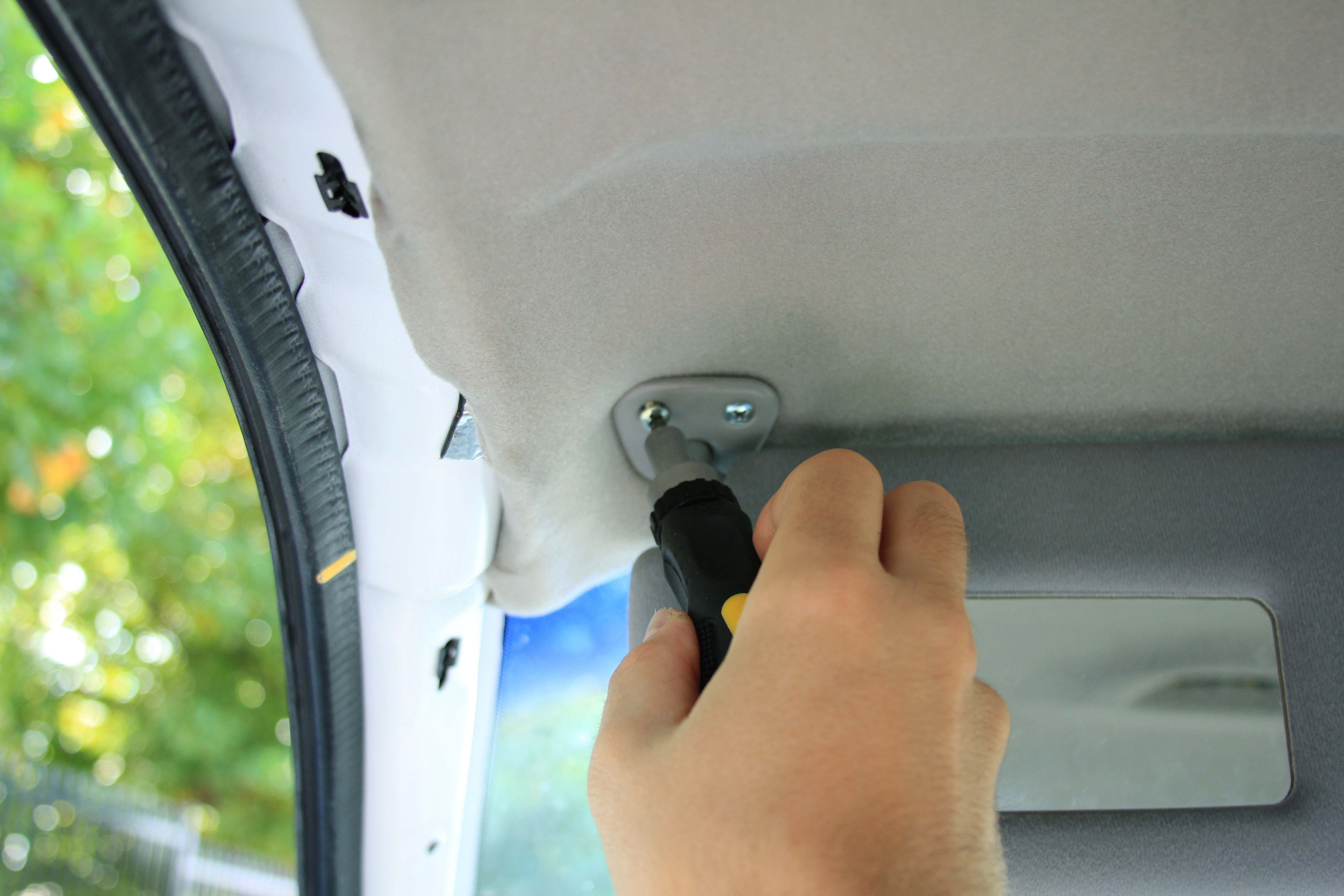 Sun Visors Fitment Next step is to install front interior lights. 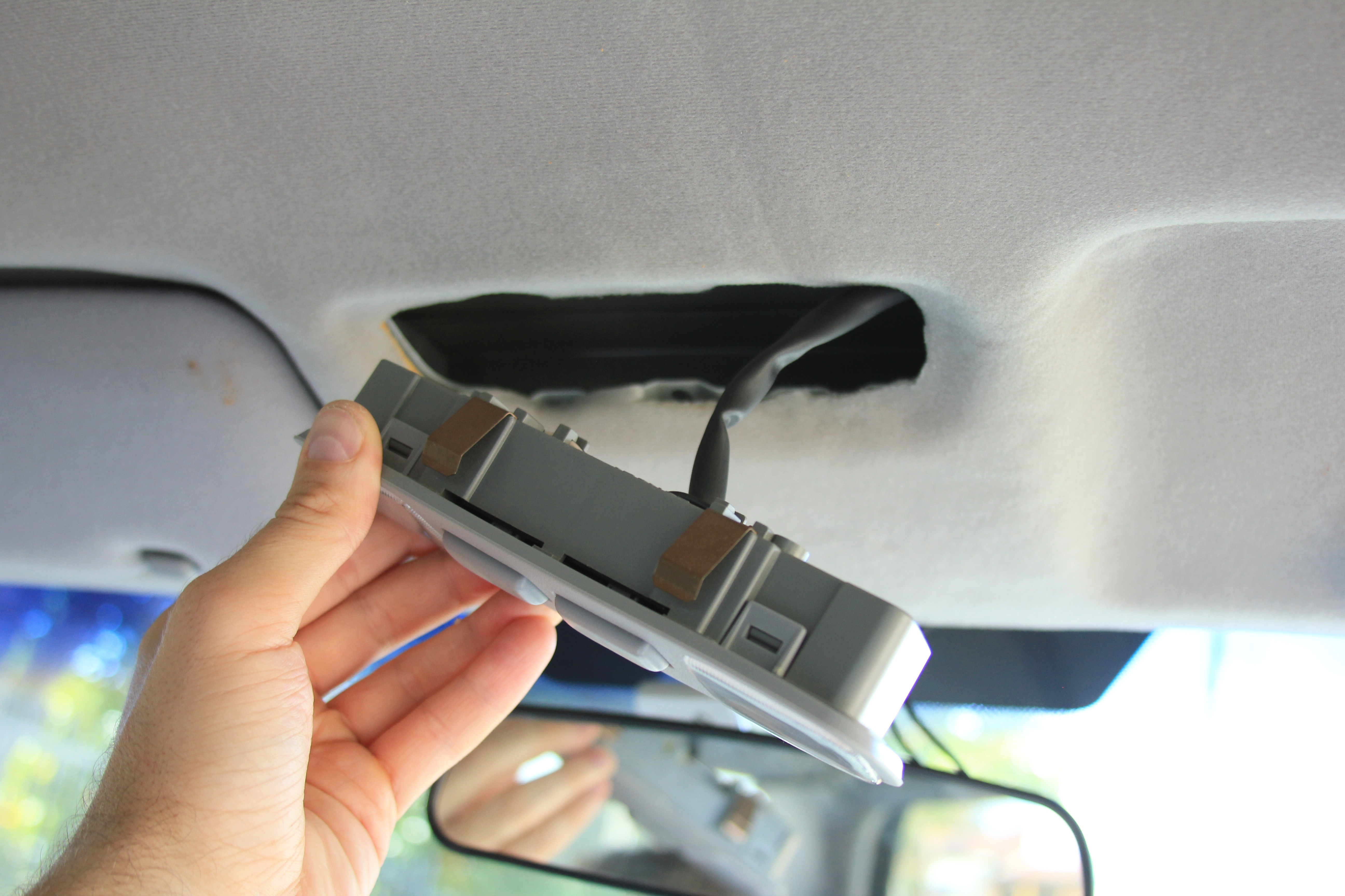 Fitting Front Interior Lights Finally installing back primary interior lights… 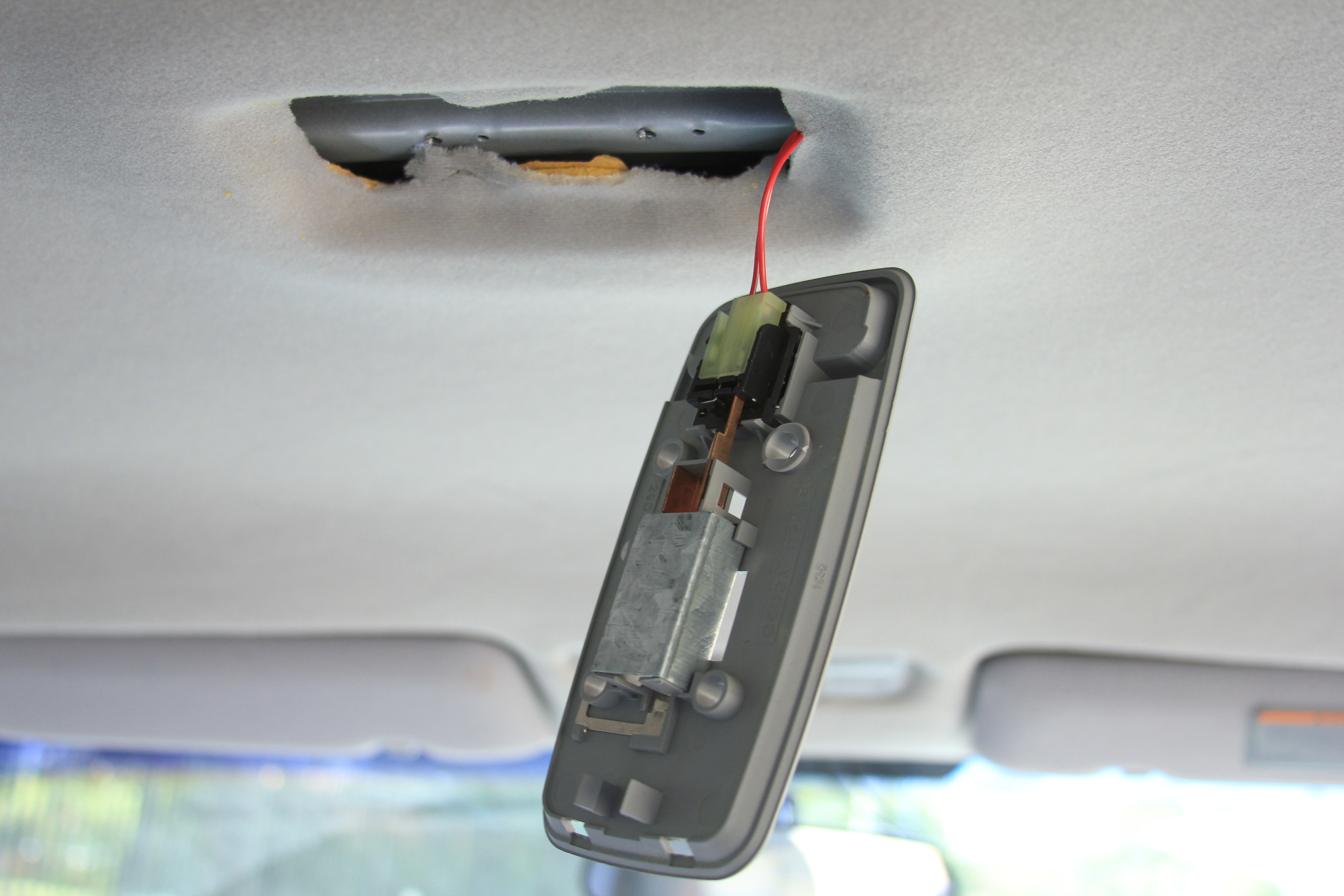 Fitting Interior Lights And firmly securing the assembly in place. 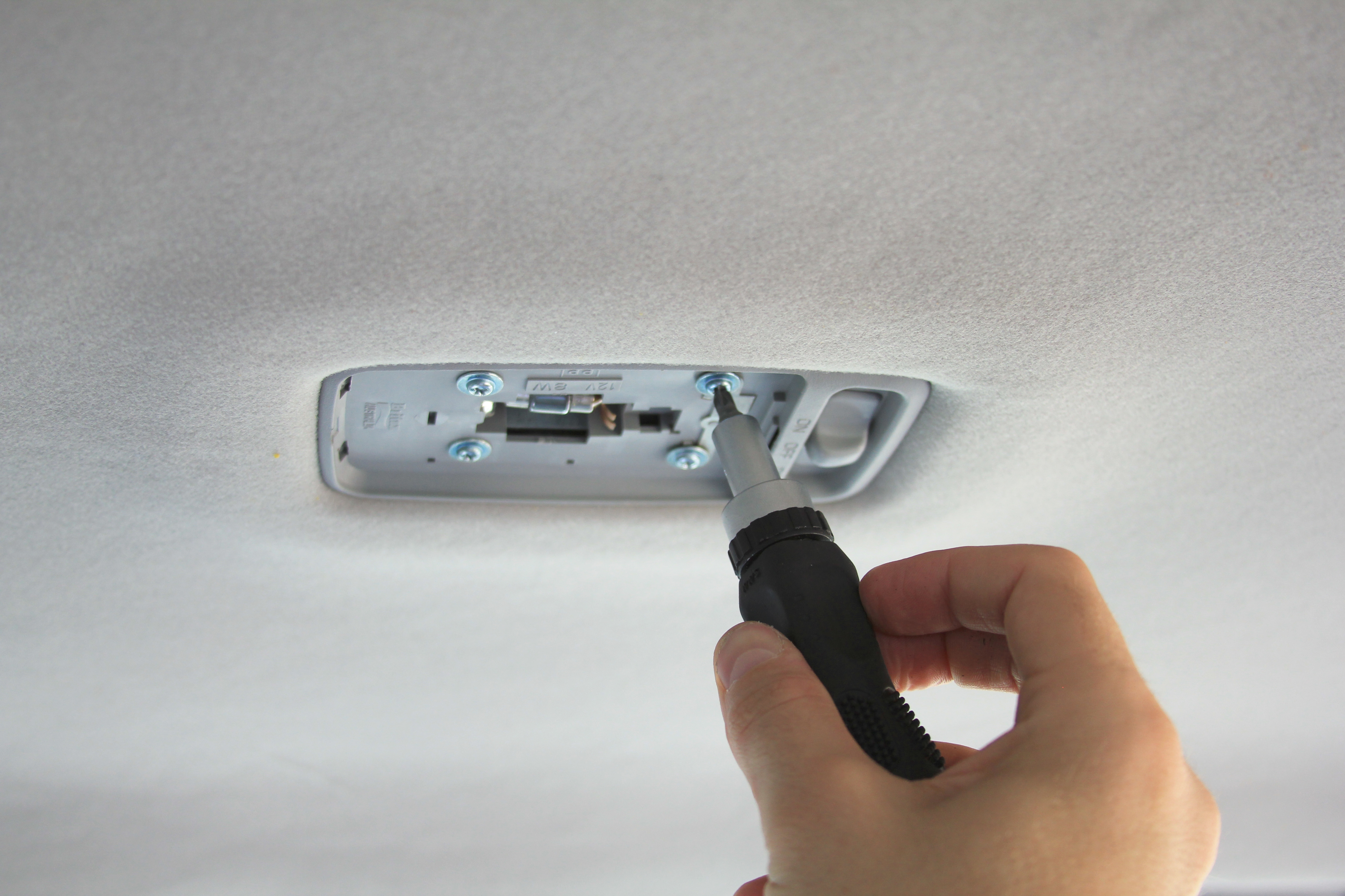 Fitting Interior Lights Just doing the final touch to the elements of interior… 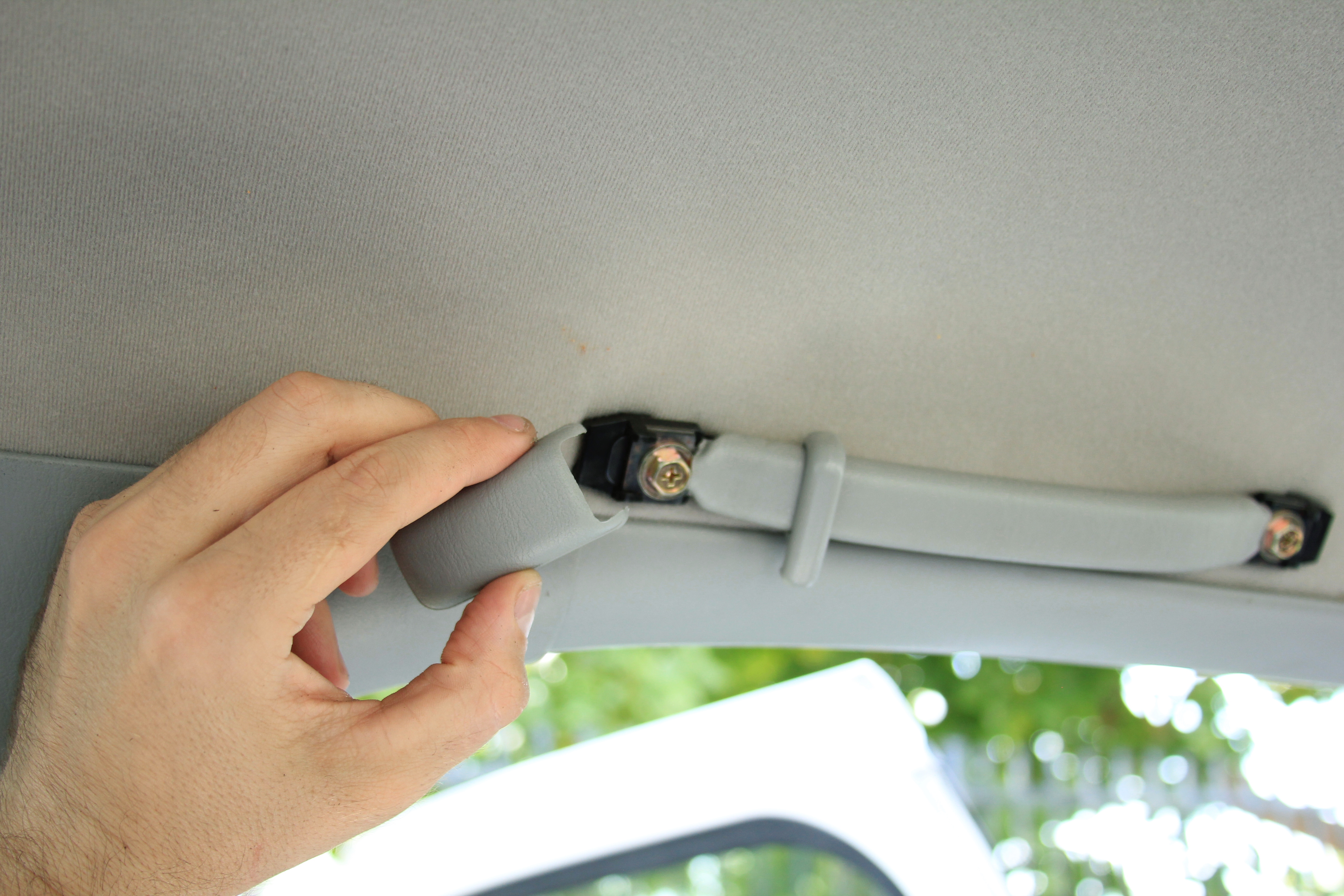 Final Touches … and the only remaining parts is plastic panels. Before fitting panels make sure that black metallic brackets are on the panel, not inside slots on a car body otherwise you won’t be able to click panels back in place. 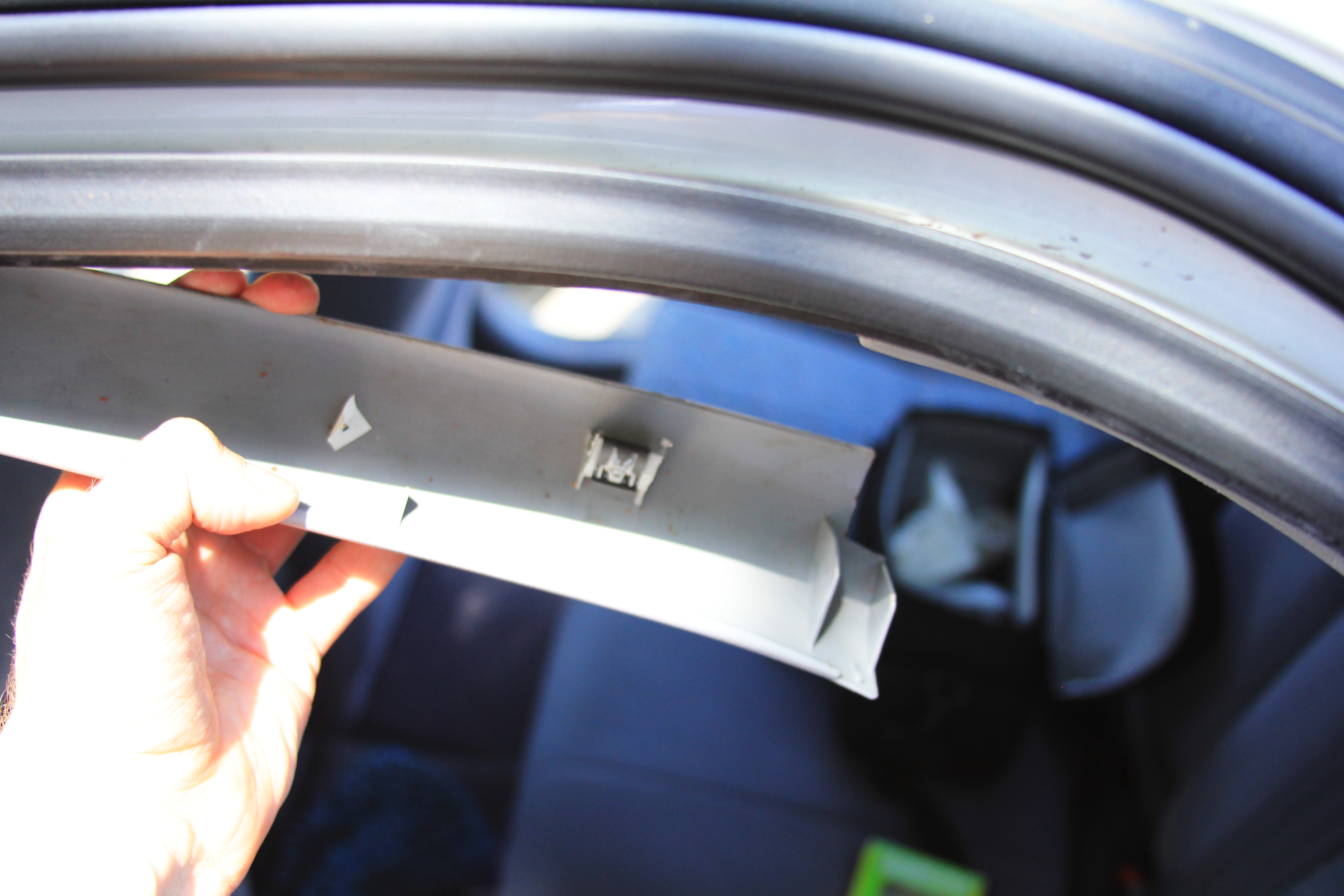 Securing Plastic Panels Put power cable going from the front camera under the right front plastic panel as shown on the picture below. The cable then will go under the dashboard to a cigarette lighter socket where it will be connected with a SCA 3 way quick connect housing. 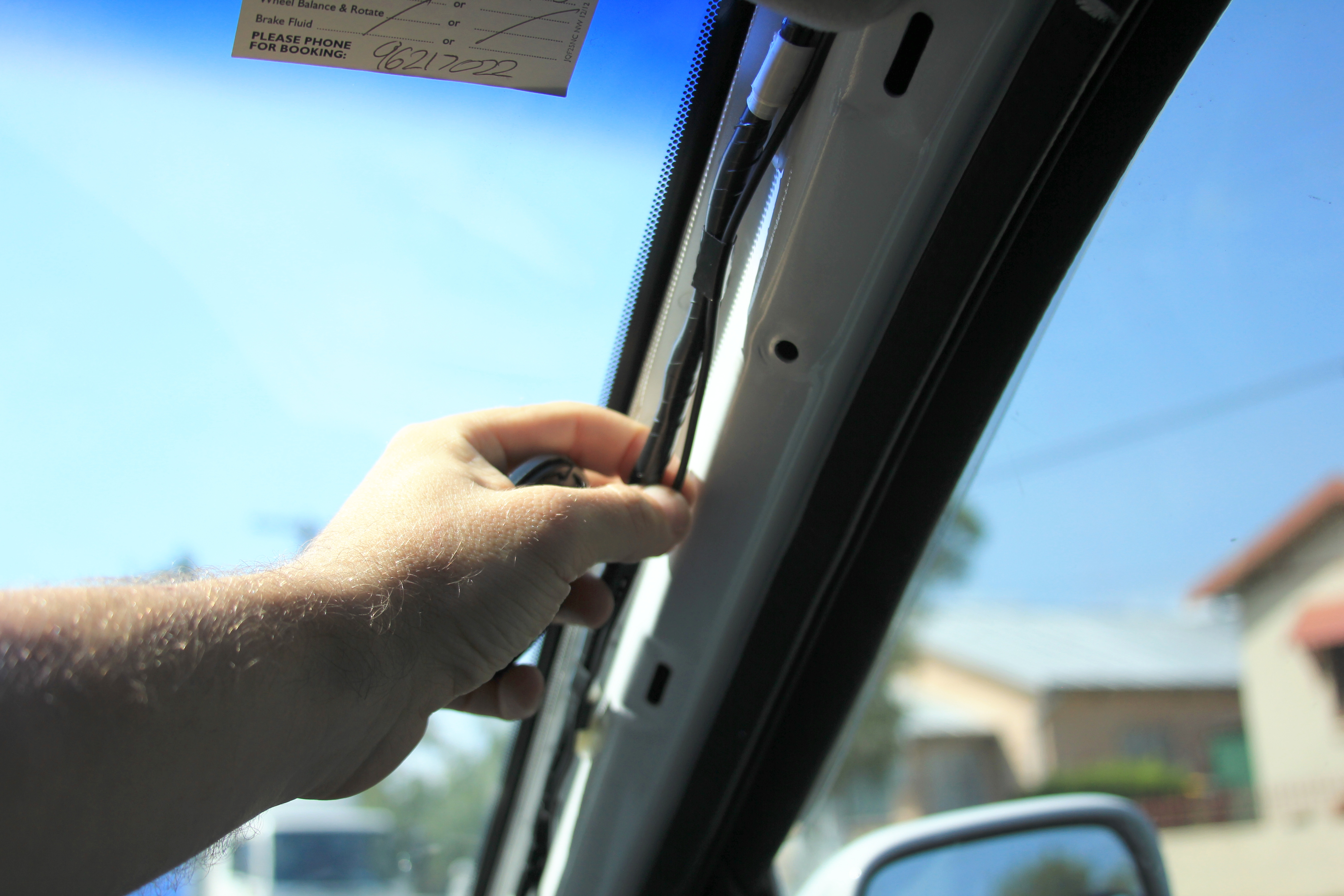 Camera Power Supply Cable The final result of the fitted front camera is shown on the picture below. It is practically unnoticeable to the driver as it is positioned behind the mirror. 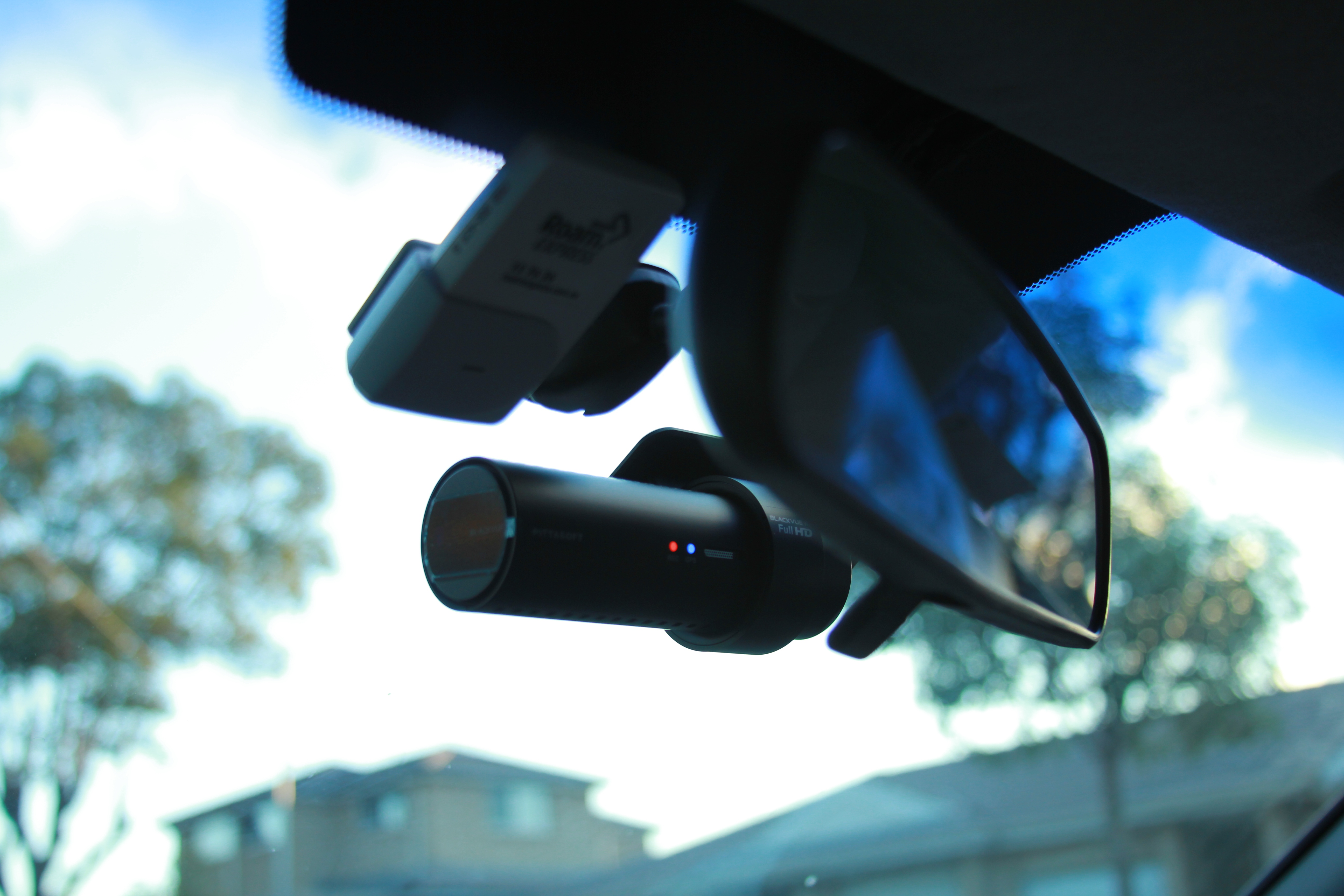 Front Camera Fitment From another angle it is clearly seen how two cables (coaxial and power) disappear behind the panel that we just put back after repair. 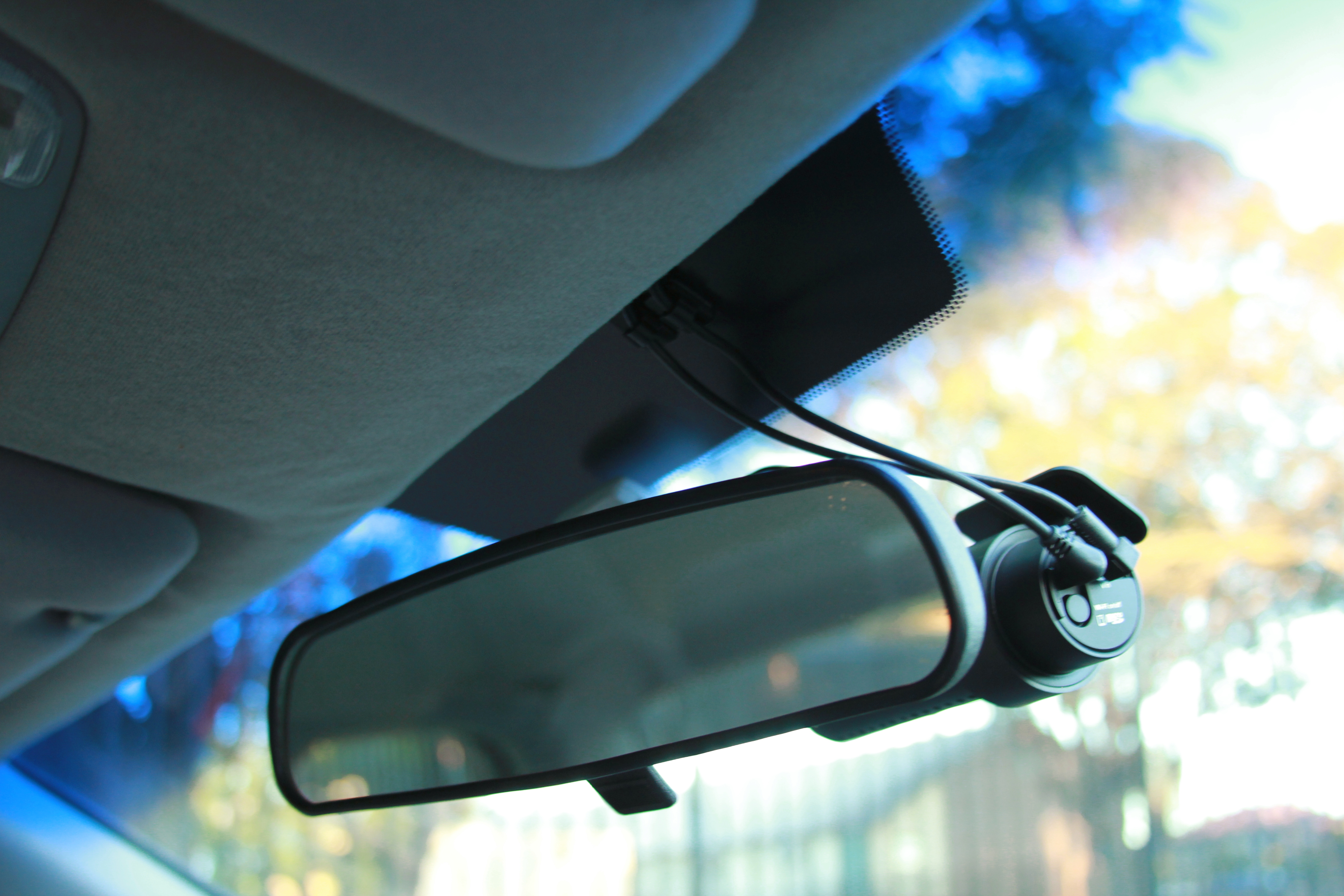 Front Camera Fitment The rear camera is also neatly mounted on the back with coaxial cable hidden under the panel.  Rear Camera Fitment The two cameras in action can be seen in the following video: Some time ago we began looking for alternative displays for our Luminardo project and got inspired by a DIY OLED interface board. The author found cheap monochrome OLED displays on Ebay, designed an interface board and wrote a C library. In addition to that some more information on driving such display type was found at DGK Electronics. The displays looked bright and thin, the board was compact and simple, the display was controlled via standard either I2C or SPI interface so we decided to give it a try. After doing a bit of search it was discovered that there were big variety of such displays including some which were already fitted on small PCBs yet the price tag was still below $10. Finally we ended up ordering couple of 128×32 displays without PCB and one 128×64 mounted on a PCB and controlled via I2C. When they eventually arrived, we realised that we actually misjudged their size – in fact they were really small, much smaller than our Luminardo so there was probably no point in designing yet another ‘Luminardo display shield’. Nevertheless, let’s get started our experiments. First of all, we need physically connect OLED display and Luminardo board. Luminardo conveniently has a designated connector for interfacing with I2C devices, it is P4. The wiring between two boards is given in the table below:
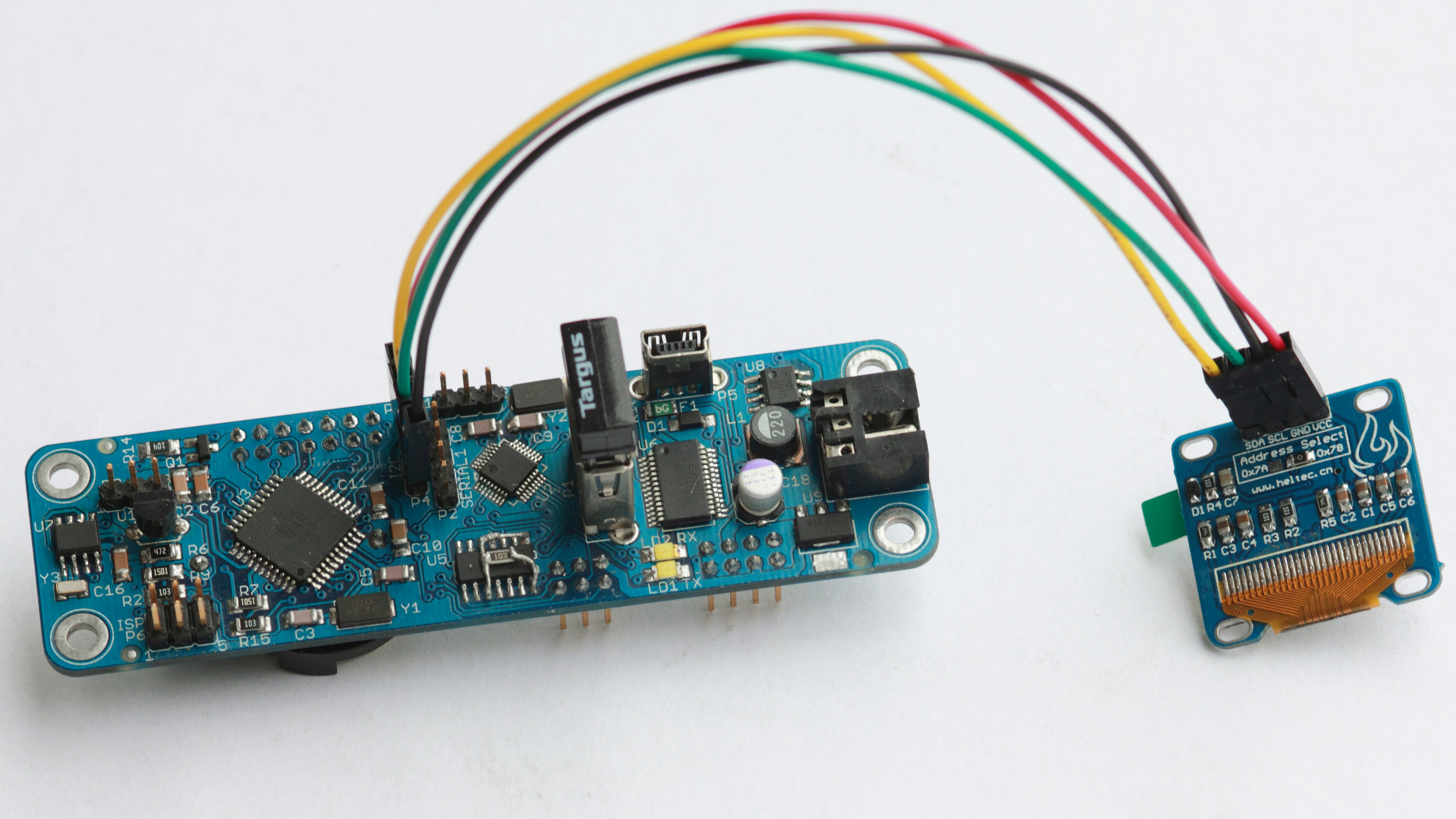 Wiring Luminardo and SSD1306 OLED Display via I2C Now we need a library to control the display. There are plenty of different flavors out there but the most comprehensive and well known is the one designed by Adafruit company which is called Adafruit_SSD1306. Well, at least the library seemed the best to us before we began using it, what is wrong with it you we learn pretty soon in this article. The installation of the library is described in great detail at Adafruit SSD1306 Tutorial. As we are experimenting with I2C version of 128×64 pixels display we will need to run SSD1306_128x64_i2c Arduino sketch. Compile it for Luminardo platform and try to run. If the display doesn’t work, try to initialise I2C interface with display.begin(SSD1306_SWITCHCAPVCC, 0x3C); // used to be 0x3D Also, note that our display doesn’t have reset pin so we defined a dummy GPIO: #define OLED_RESET 0 Adafruit_SSD1306 display(OLED_RESET); Once the display becomes alive and Luminardo happily runs Adafruit demo it is time to create our own picture. Let’s say, we want to design a ‘Magictale’ logo. First, find or draw a picture of icosahedron as the example below:  An Icosahedron The picture is then resized and cropped to fit 128×64 pixels using GIMP and then converted to monochrome using ImageMagick with the following command: convert icosa.gif -monochrome monochrome_icosa.gif … and resulting in the following picture:  Icosahedron Monochrome Next step then is to convert monochrome picture into C byte array with help of Picture To C Hex Online converter:  Picture To Byte Array Online Converter We almost ready to send our picture to the display. However, there is one inconvenient moment: Adafruit’s library has a method
static const unsigned char PROGMEM
Clock[] =
{
62, 63, //62x63 pixels
0x00,0x00,0x01,0xff,0xfc,0x00,0x00,0x03
...
,0x00,0x00,0x00,0x0f,0xc0,0x00,0x00,0x03
};
And the generic function-wrapper around
void drawBitmapCentred(const uint8_t *bitmap, uint16_t color)
{
uint8_t b_width = pgm_read_byte(bitmap++);
uint8_t b_height = pgm_read_byte(bitmap++);
display.drawBitmap((display.width() - b_width) / 2, (display.height() - b_height) / 2, bitmap, b_width, b_height, color);
}
Next step would be to replace standard Adafruit splashscreen with something else. You won’t find splashscreen bitmap explicitly defined anywhere. The trick is in framebuffer which is defined as The pixels in framebuffer don’t go in the same order as we have it in our bitmaps – from left to right and from top to bottom, so we can’t just replace the content of the buffer with our new picture as it will result in chaotically scattered pixels. But the good thing is that we don’t need to know the format of the framebuffer – all we need to do is to draw a new logo using
void Adafruit_SSD1306::bufToSerial()
{
for (uint16_t i = 0; i < SSD1306_LCDHEIGHT * SSD1306_LCDWIDTH / 8; i++)
{
Serial.print("0x");
Serial.print(buffer[i], HEX);
Serial.print(", ");
}
}
Now, when we get framebuffer dump, we just copy-and-paste it to 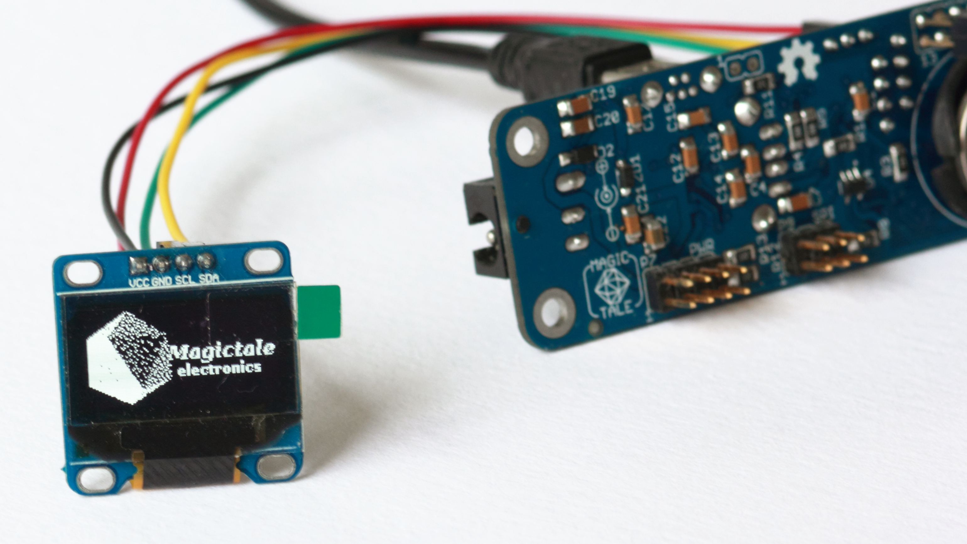 Luminardo and SSD1306 OLED Display Custom Splashscreen Now we came to a point when it would be extremely useful to define more than one font. The standard one embedded into the library is only 5×7 pixels and while there is a functionality to specify font size everything bigger than size one looks really ugly. It would be very handy to have more than just one font at our disposal, for example, a higher definition font which simulates seven segment digits. We are not going to draw new font and just try to reuse the one from UTFT library defined as 2Kb
// SevenSegNumFont
// Font Size	: 32x50
// Memory usage	: 2005 bytes
// # characters	: 10
static const unsigned char sevenSegNumFont[2005] PROGMEM={
0x20,0x32,0x30,0x0A, 1 << FONT_OPT_BIT_DIR,

//the font actually starts here
0x00,0x00,0x00 ...
};
Let’s have a closer look at the fifth byte in font’s descriptor. It has two options, In order to support multiple fonts,
#if ARDUINO >= 100
size_t Adafruit_GFX::write(uint8_t c) {
#else
void Adafruit_GFX::write(uint8_t c) {
#endif
const uint8_t* fontpntr = _currfont;
uint8_t c_width = pgm_read_byte(fontpntr++);
uint8_t c_height = pgm_read_byte(fontpntr++);

if (c_width > c_height)
{
uint8_t tmp_width = c_width;
c_width = c_height;
c_height = tmp_width;
}

if (c == '\n') {
cursor_y += textsize * c_height + _fontPitch;
cursor_x  = 0;
} else if (c == '\r') {
// skip em
} else {
drawChar(cursor_x, cursor_y, c, textcolor, textbgcolor, textsize);
cursor_x += textsize * c_width + _fontPitch;
if (wrap && (cursor_x > (_width - textsize * c_width + _fontPitch))) {
cursor_y += textsize * c_height + _fontPitch;
cursor_x = 0;
}
}
#if ARDUINO >= 100
return 1;
#endif
}

// Draw a character
void Adafruit_GFX::drawChar(int16_t x, int16_t y, unsigned char c,
uint16_t color, uint16_t bg, uint8_t size)
{
const uint8_t* fontpntr;

fontpntr = _currfont;
uint8_t c_width = pgm_read_byte(fontpntr++);
uint8_t c_height = pgm_read_byte(fontpntr++);
uint8_t start_chr = pgm_read_byte(fontpntr++);
uint8_t end_chr = start_chr + pgm_read_byte(fontpntr++);
uint8_t fnt_options = pgm_read_byte(fontpntr++);

uint8_t bt_msk = 0x1;
if ((fnt_options >> FONT_OPT_BIT_DIR) & 0x1 == 1) bt_msk = 0x80;
bool column_first = false;
if ((fnt_options >> FONT_OPT_COLUMNS) & 0x1 == 1) column_first = true;

if (c < start_chr || c >= end_chr) return;

c -= start_chr;

if((x >= _width)            || // Clip right
(y >= _height)           || // Clip bottom
((x + (c_width + 1) * size - 1) < 0) || // Clip left
((y + (c_height + 1) * size - 1) < 0))   // Clip top
return;

uint8_t line;
uint8_t x_resolution = c_width / 8;
if (c_width % 8 != 0) x_resolution++;

for (uint8_t i = 0; i < c_height; i++)
{
for (uint8_t j = 0; j < x_resolution; j++)
{
uint16_t offset = c * x_resolution * c_height + i * x_resolution + j;
line = pgm_read_byte(fontpntr + offset);

for (int8_t k = 0; k < 8; k++)
{
if (line & bt_msk)
{
if (size == 1) // default size
{
if (column_first)
drawPixel(x + i, y + j * 8 + k, color);
else
drawPixel(x + j * 8 + k, y + i, color);
}else
{  // big size
if (column_first)
fillRect(x + ((i * 8 + k) * size), y + (j * size), size, size, color);
else
fillRect(x + ((j * 8 + k) * size), y + (i * size), size, size, color);
}
}
else if (bg != color)
{
if (size == 1) // default size
{

if (column_first)
drawPixel(x + i, y + j * 8 + k, bg);
else
drawPixel(x + j * 8 + k, y + i, bg);
}else
{  // big size
if (column_first)
fillRect(x + ((i * 8 + k) * size), y + (j * size), size, size, bg);
else
fillRect(x + ((j * 8 + k) * size), y + (i * size), size, size, bg);
}
}

if (bt_msk == 1) line >>= 1;
else line <<= 1;

}
}
}
}

void Adafruit_GFX::setFont(const uint8_t* fnt, uint8_t fontPitch)
{
_currfont = fnt;
_fontPitch = fontPitch;
}
The final library support three full-blown fonts: 5×7 (smallFont), 8×12 (meduimFont) and 16×16 (bigFont). There is also a way to specify pitch – a distance in pixels between adjacent characters so in real life there is more than 3 differently looking fonts. In addition, there are 10 32×50 digits in seven segment style which make numbers much more neat: 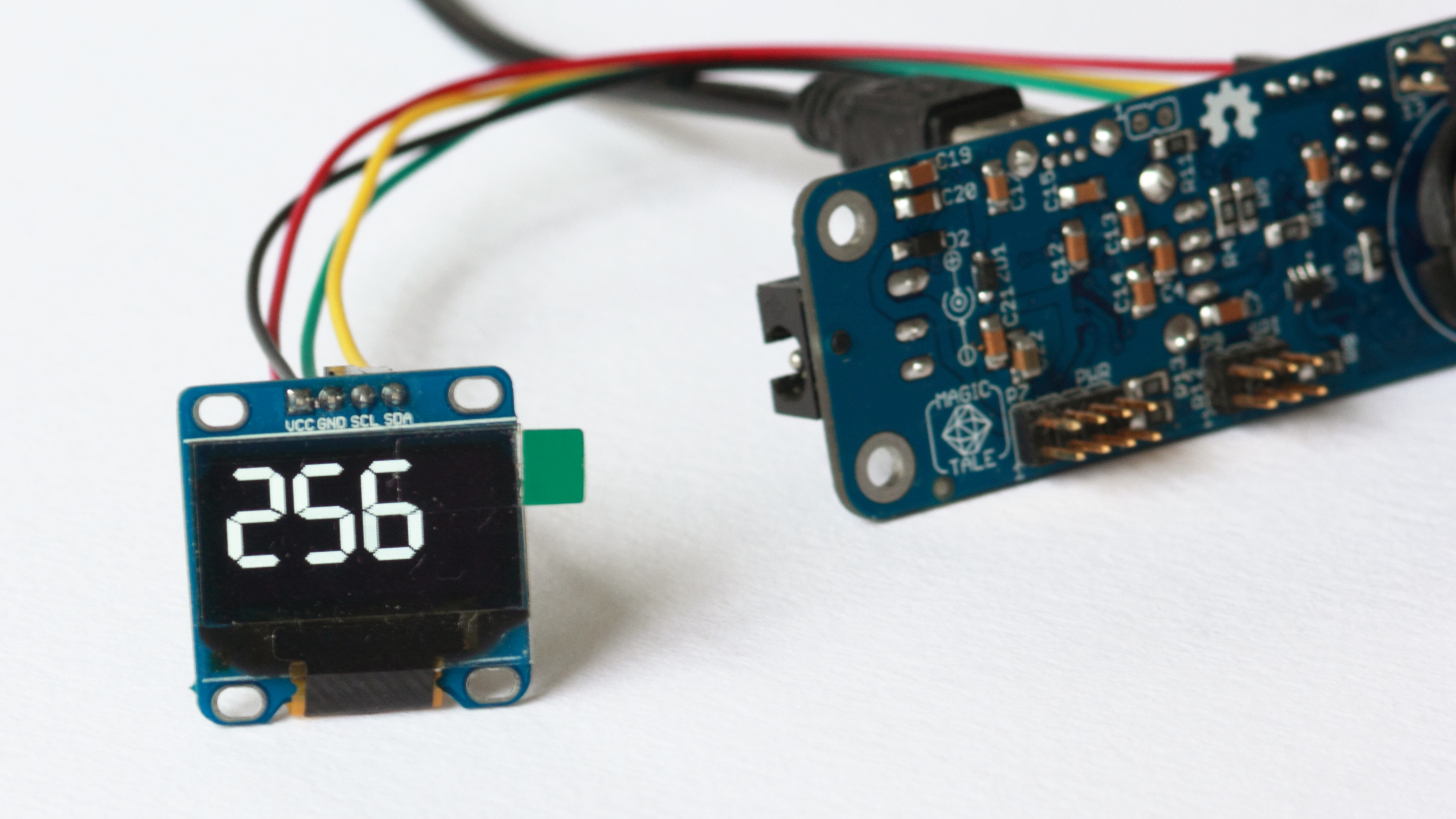 Luminardo and SSD1306 OLED Display – 7 Segment Large Digits If you create a counter from 0 to 999 you will notice that it takes visibly longer time to render three big seven segment digits that just two or one. Given, that in order to commit changes to the display same about of data (whole frame buffer) is sent via I2C interface it means that our rendering mechanism in RAM is even slower than I2C bus (which is relatively slow thing). This is not good obviously and there should be some optimisations to the code to be done. But let’s leave it for the next exercise. Downloads:1. Adafruit_Luminardo_SSD1306_2015_04_06.zip – supports multiple fonts; 2. Adafruit_Luminardo_SSD1306_Blink_2015_04_08.zip – supports multiple fonts and blinking but uses 2Kb for primary and secondary frame buffers rather than just 1K for a single buffer; Just recently we faced a problem when in order to lock/unlock doors of our Toyota Camry 1998 with a keyless entry remote we virtually had to be… inside the car as the remote’s effective radius shrank down to about 200 mm and even less! To make it worse, every subsequent button press led to even weaker signal up to a point when the remote was turning into an absolutely useless accessory. The cause for this was undoubtedly a battery in the 17-year-old remote. Quick Internet research suggested that a replacement for ‘such an old car’ is put in a ‘rarity’ category if judge by absolutely mindblowing price tag which normally starts from $80 on ebay! What is even more interesting, such things are claimed to be ‘genuine Toyota remotes’ but there is no a single word about their manufacturing date so we had some doubts about their longevity. And given that we needed to replace two remotes the prospect of paying $160 looked really daunting. So we decided to chose an alternative path. First challenge was to open the shell to get access to the PCBA and battery. Two parts were fused together so chances of damaging plastic were relatively high. That is why before opening the thing we googled for a replacement and came out with 2 x TOYOTA Remote 1B shells for just $19.50 and free shipment on ebay. Going a bit further, two Lithium batteries cost us $0.99 each so the total typical expenses would look like this:
To crack open the shell we used a couple of screwdrivers, one was thinner and used to make the seal weaker, the second one was used as a leverage. While doing it, keep in mind two things: 1) never mind the damage to the shell and 2) remember, that there is PCBA inside the shell which must be in good condition after the operation. The picture below shows an opened remote: 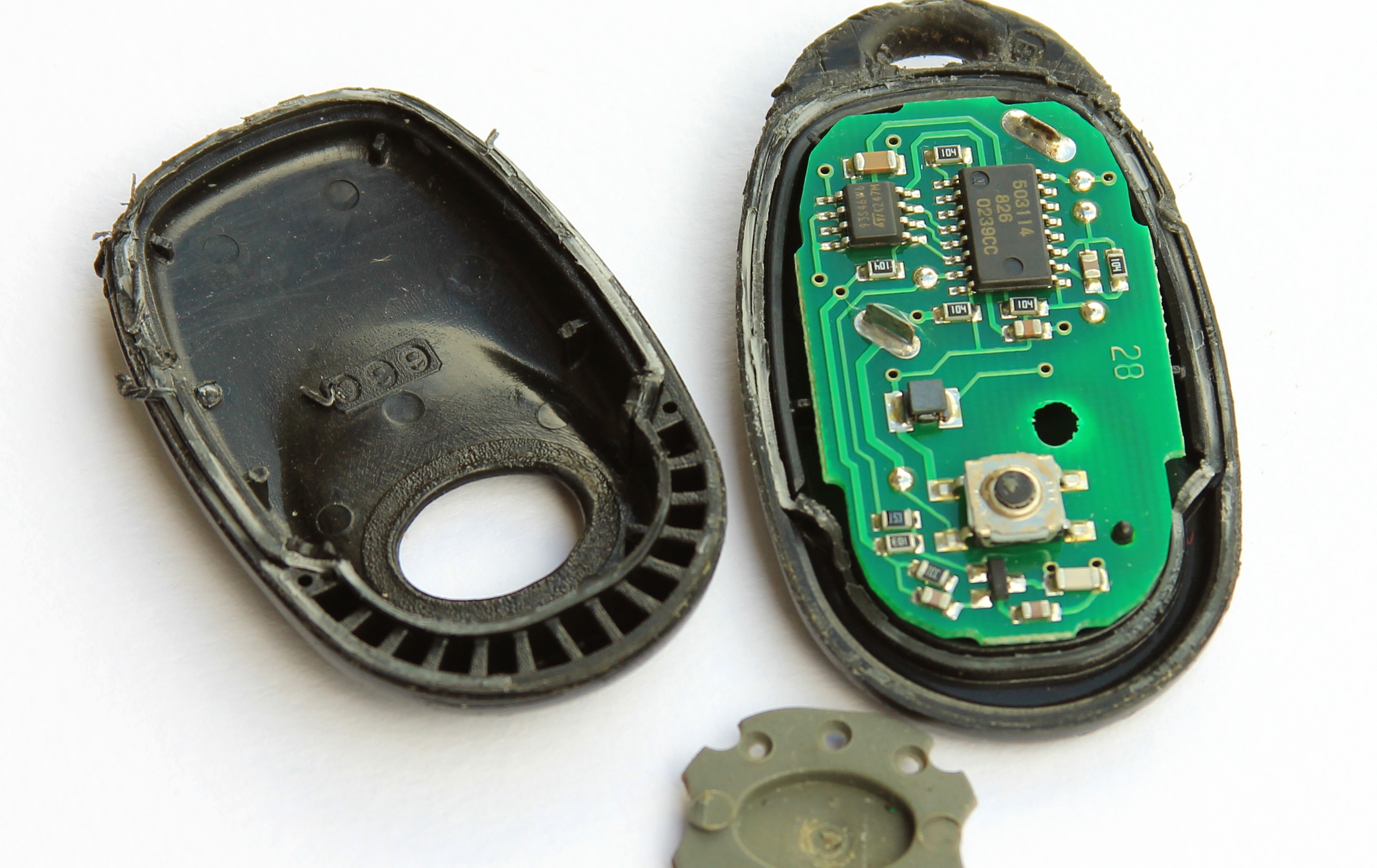 Keyless Entry Remote Cracked Open On the next picture remote’s PCBA successfully extracted from the shell: 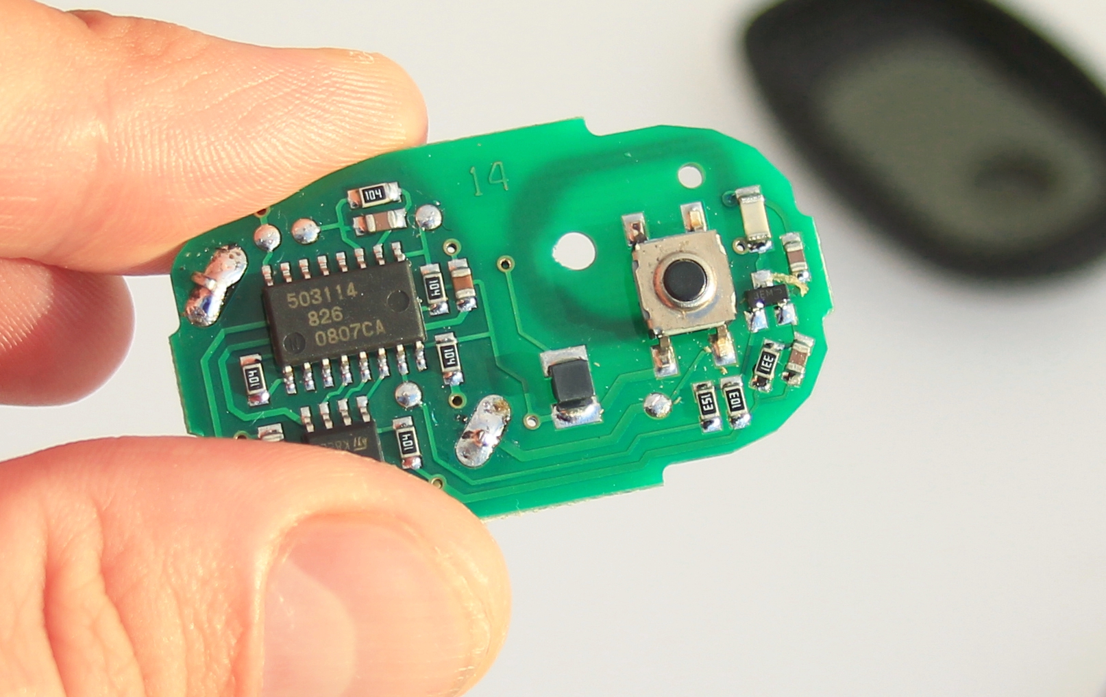 Toyota Camry 1998 Keyless Entry Remote PCBA … and the opposite side of the PCBA reveals that there is no battery holder so we would need to use a soldering iron in order to do the replacement: 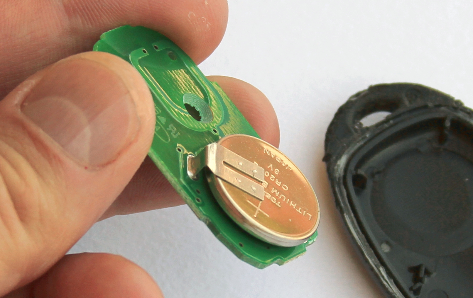 Toyota Camry 1998 Keyless Entry Remote PCBA Battery The next picture below shows PCBA and battery for replacement. In our case it was CR2032 with pins. Be careful when ordering such batteries – make sure that the distance between two pins and battery’s height is what you really need. When soldering, try to minimise battery’s overheating. And of course ensure that the polarity is correct: 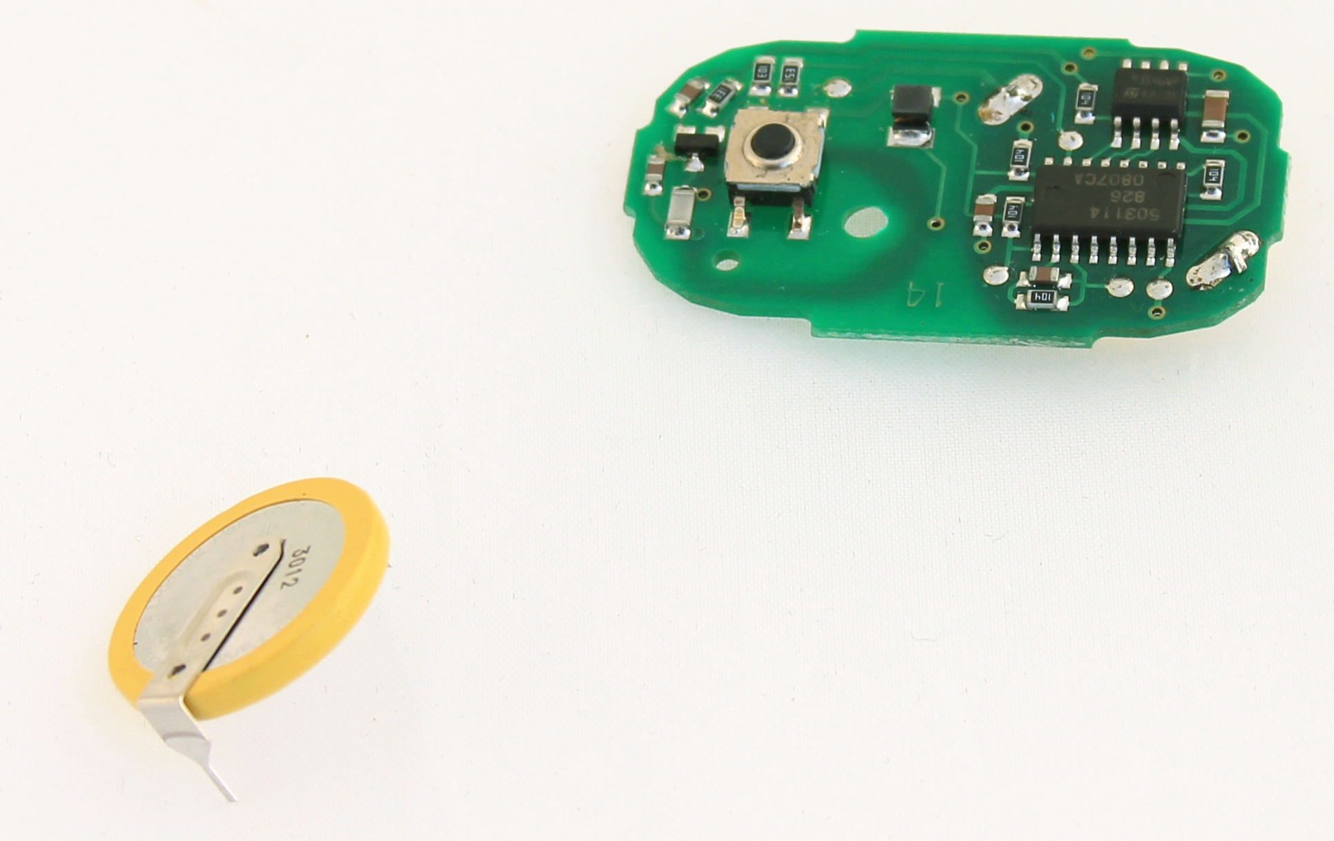 Toyota Camry 1998 Keyless Entry Remote Before Battery Replacement The actual soldering is anything but difficult – all that needs to be done is to desolder and solder two pins: 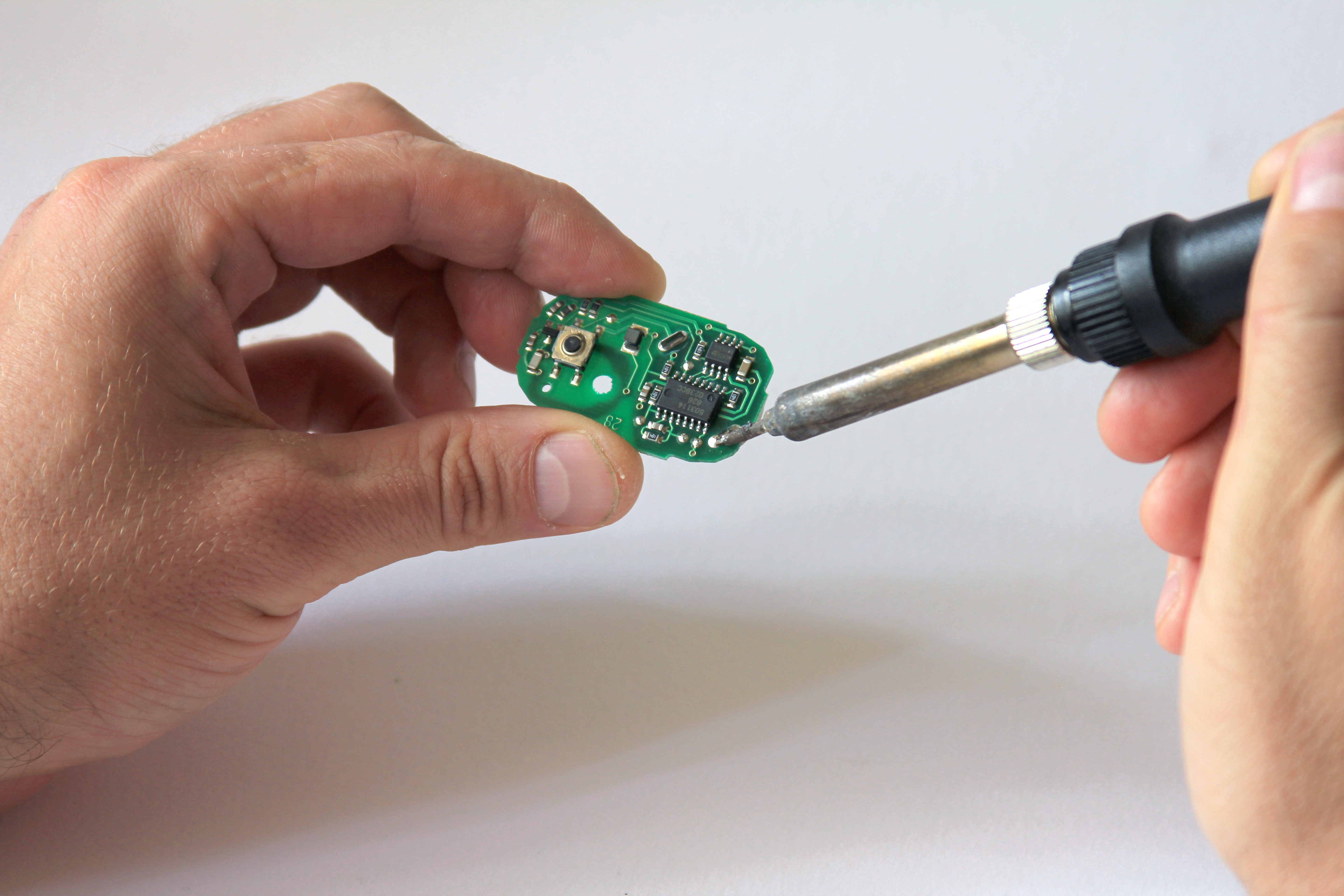 Soldering New Battery When soldering is done, trim both pins: 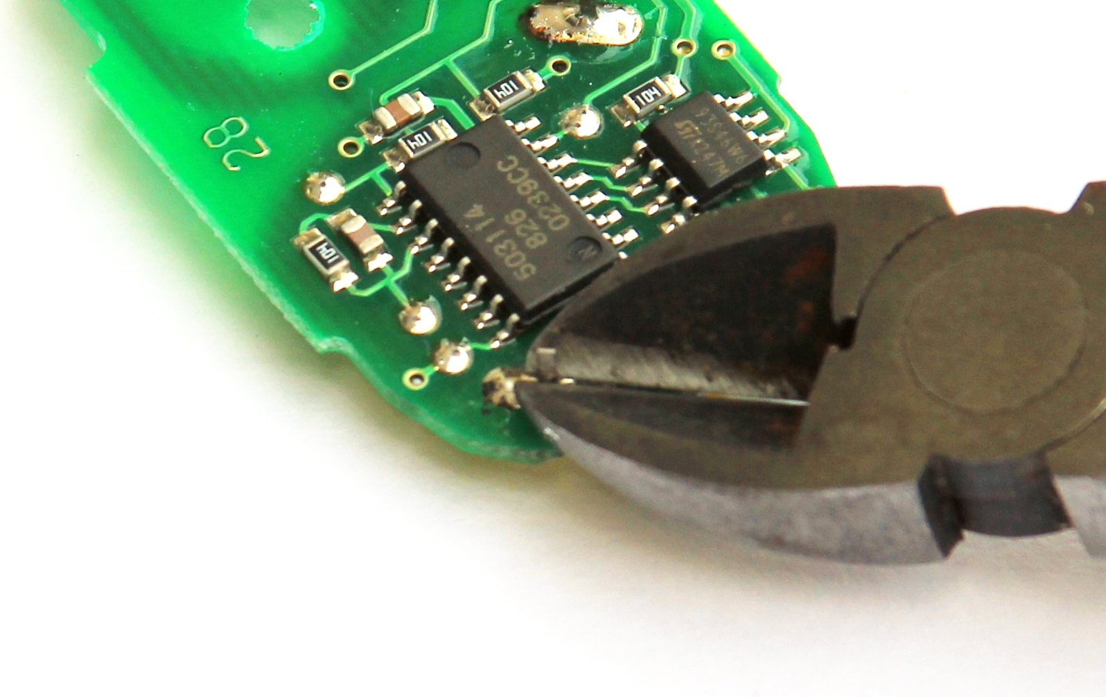 Trimming Battery Pins The battery is finally replaced. Before putting into a new shell it is a good idea to go to your car and check that it works indeed: 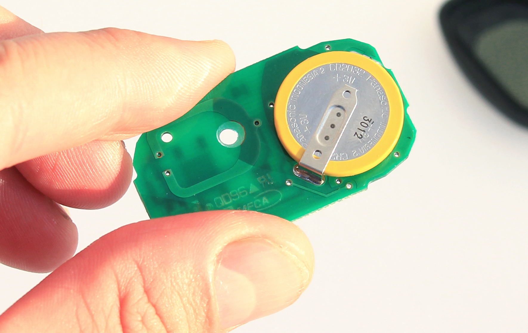 Toyota Camry 1998 Keyless Entry Remote After Battery Replacement Final step: putting the PCBA in a shell. It is a good idea to make sure that there are no chances for short circuit when two plastic parts hold your PCBA in place. In our case we also needed to trim rubber button as our microswitch on the PCBA remained always on. 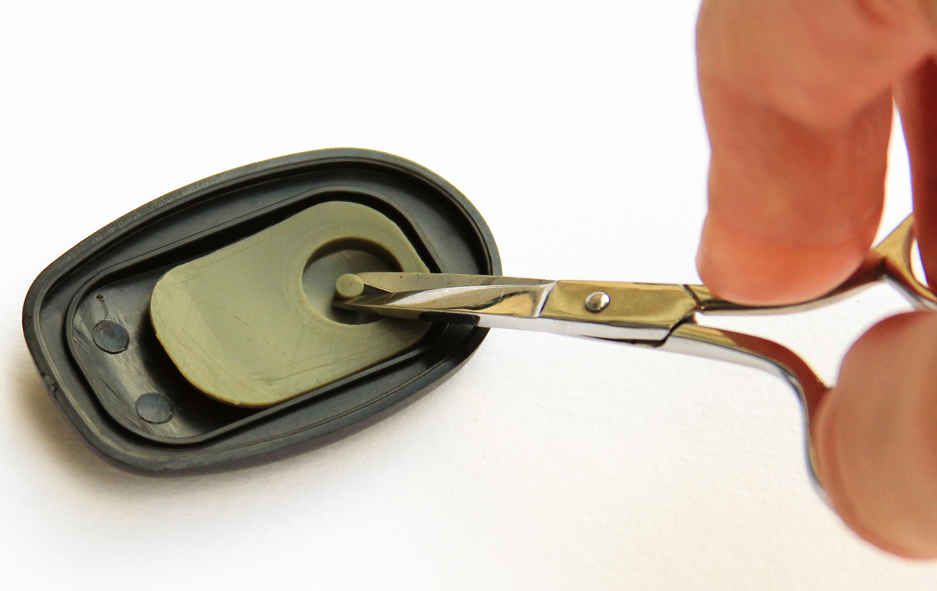 Trimming Rubber Button The result of our effort is shown below: 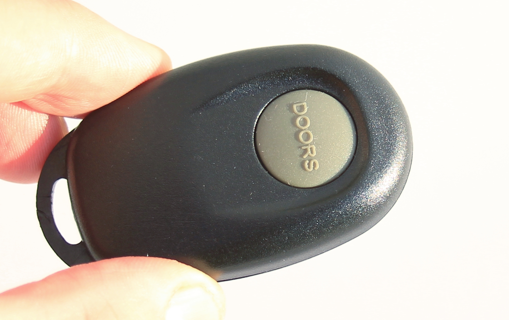 Toyota Camry 1998 Keyless EntryRemote In New Case Although in this post we described set of actions for a specific make and model, we believe that the idea is applicable to the majority of modern (and not very modern) cars. The same basic principle remains: quite often it is more cheaper to replace just a few parts rather than replacing the whole module or accessory. In addition, you will gain more skills and dump less which is also beneficial for our planet. Our site has been moved recently from |
|||||||||||||||||||||||||||||||||||||||||||||||||||||||||
|
Copyright © 2024 Magictale Electronics - All Rights Reserved 

|
|||||||||||||||||||||||||||||||||||||||||||||||||||||||||