Grand Prize Winner
(Dec 2012)
Second Prize Winner
(July 2012)
Donations Development in general requires time and money. Development of opensource projects is not an exception. To keep this online resource alive we heavily rely on your donations. If you feel like supporting us please make a donation.
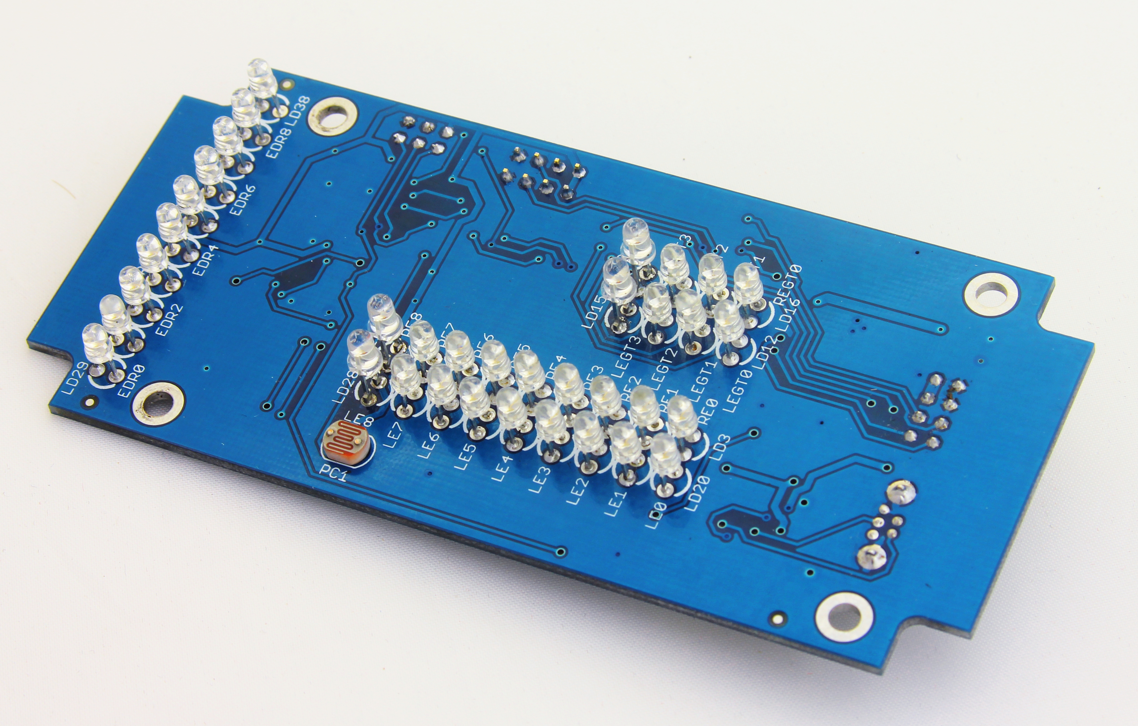
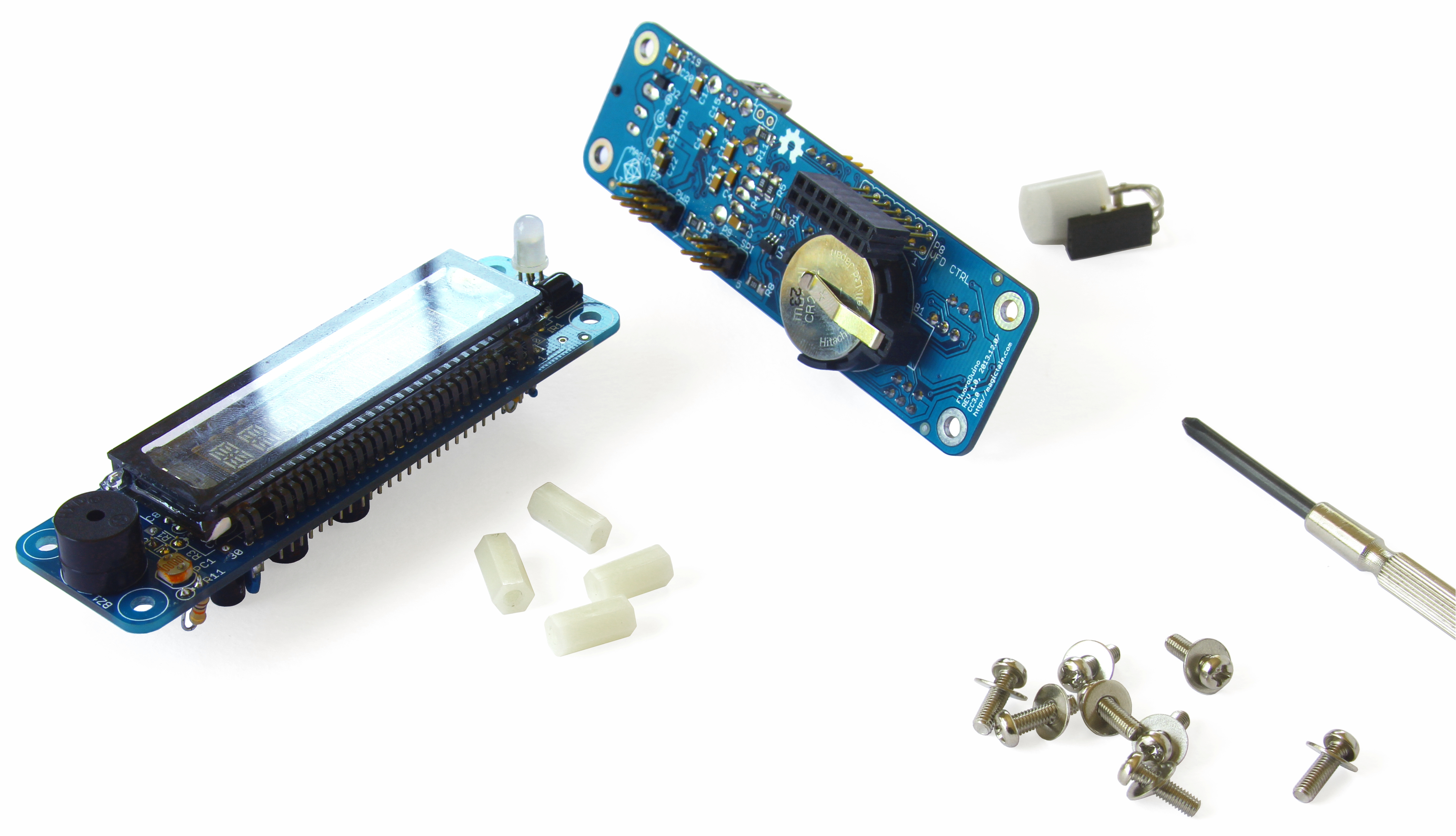
First Pilot Display PCB is finally assembled and tested. As it usually happens with revisions 1.0 there are several things that have been overlooked during design. Good news is that all issues are minor and don’t impact main functionality. Here are the discovered issues:
a) First of all, FT232 is not powered when USB cable is not connected resulting TXLED and RXLED outputs being pulled low and as a consequence LD1 and LD2 are constantly switched on. Connecting USB cable puts both LEDs to the desired (switched off) states even when the cable is then unplugged. This is annoying but given that both LEDs are powered with 1K resistors in series, it doesn’t make much of a difference in power consumption even with both LEDs being permanently switched on.
b) The next problem though is ST3232BSOIC16 which shares RX-I and TX-O signals with FT232. ST3232BSOIC16 never puts its outputs into hi-z state and therefore microprocessor ATMEGA1284PA can’t receive data from FT232 which is essence means that USB interface cannot be used for firmware updates, maximum that we can get is a debug output through USB. However, firmware updates still can be done via RS232 interface for the left engine (TX_LEFT and RX_LEFT). In the next revision it will be worth adding a jumper to manually switch between serial and USB interfaces;
c) R5 resistor doesn’t make much sense and better to be replaced with 0.1uF ceramic capacitor;
d) Both MAX6957 are not designed to put their DOUT outputs into hi-z mode when not selected by SS which creates conflicts on the SPI bus when the microprocessor is being programmed via ISP header. We managed to program the microprocessor by cranking up VCC to 5V via ISP header. Once the bootloader is programmed, there is no need in ISP anymore as from that point the firmware can be updated via RS232 interface without need to use external ISP programmer;
e) Really strange and unexpected issue – red LEDs are slightly bigger than green and orange ones despite they all are of the same form factor. Attempts to find another type of red LEDs resulted in the same slightly bigger sizes!
f) LEDs are really difficult to solder precisely so it would be worth using LED spacers for the next boards;
g) At the end of this design cycle the customer expressed a desire to have opto-isolation for both RS232 ports so looks like that ST3232BSOIC16 would need to be replaced with something else;
The DC-DC converter is capable of delivery up to 1A @ 3V3 and was successfully tested under maximum load by switching all LEDs simultaneously at maximum current of 20mA per LED. No excessive power dissipation is under maximum load – all chips remain cold when touching with a finger.
Fully assembled board is shown on the pictures below.
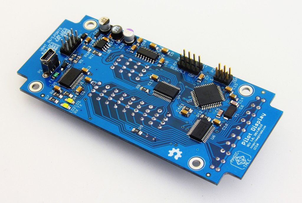 Pilot Display PCBA Bottom 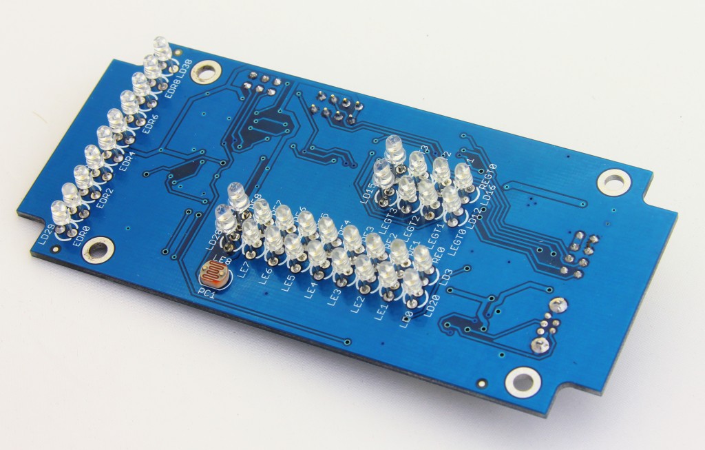 Pilot Display PCBA Top
Pilot Display Rev.1.0 PCBs finally arrived. At a first glance nothing is terribly wrong, everything seems to be fine which is a good start. However, there is always something in rev1.0 boards or schematics so will see what the subsequent assembling process and preliminary test bring us. As always, Itead Studio PCB manufacturing service has been used, they made and shipped 6 PCBs instead of promised 5.
This is what the PCBs look like:
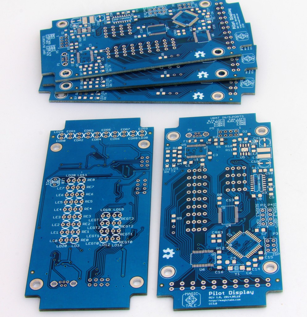 Pilot Display bare PCBs Wait for more upcoming updates on this project.
Just recently by a pure accident we became involved into very unusual project. Willing to become known to some degree amongst the local Sydney electronics enthusiasts we decided to take part in one of the community projects and help to build something. It didn’t take much time to wait for someone who posted a request asking for assistance to design a LED display panel for engine health status indication. At a first glance it looked like a toy for a remotely controlled plane equipped with a miniature turbine engine. However, it soon turned out to be more serious: the panel was supposed to indicate health status of a full scale twin turbine engine being part of a personal turbine powered aircraft! Display was required to show RPM and temperature for both engines individually and ‘flight time’. All information was requested to be represented by columns of super bright LEDs, the solution would have to be be power efficient, receive data streams from both ECUs (Engine Control Units) via regular RS232 ports, have a capability of firmware update and work in wide range of input voltages (with the efficiency peak somewhere in 15…16V range as it is a typical voltage of the aircraft’s onboard lithium battery).
After doing some preliminary experiments with multiplexed displaying technique we got unsatisfactory results for LED brightness under direct sunlight and decided to go for static indication by using specialised MAX6957 chips which also allow controlling current flowing through each individual LED and therefore allow for programmatically adjustable brightness. On top of that we decided to use USB to serial converter for easier firmware updates/debugging and a photo resistor acting as a light sensor. And here is the result of our effort.
The circuit diagram of the display panel is given below.
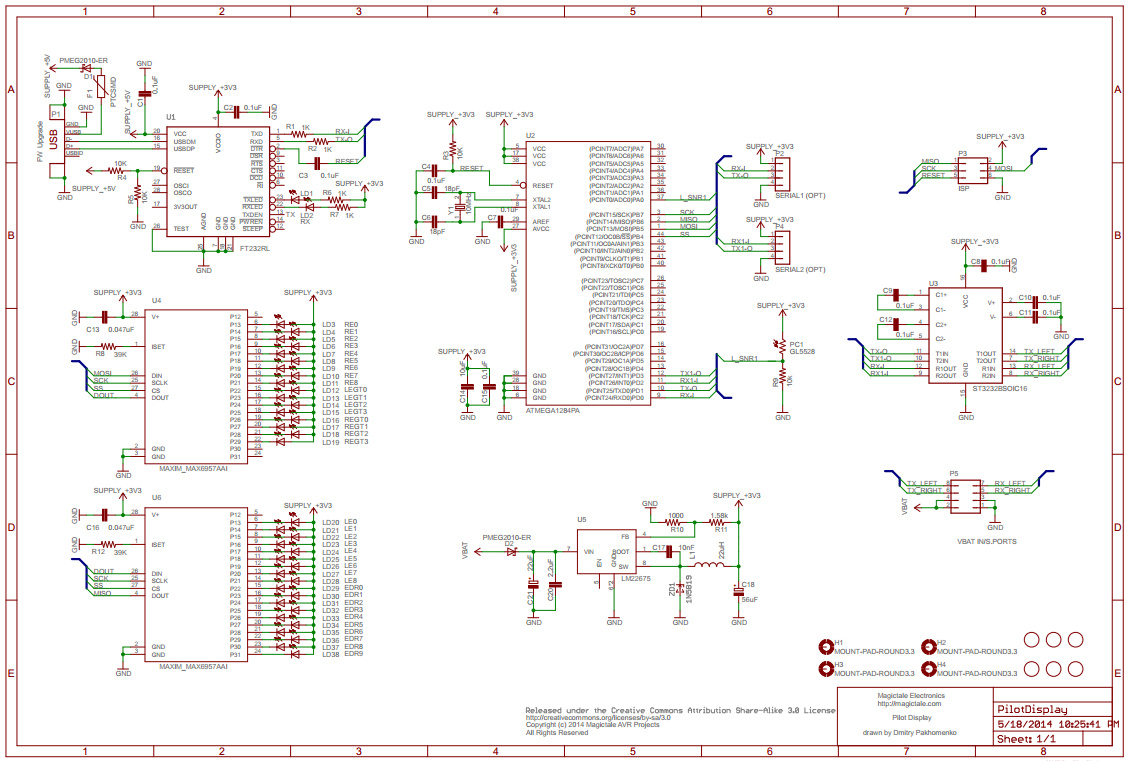 Pilot Display CircuitDiagram Rev.1.0 The PCB layout is done on two layers. Component placement for top and bottom sides are given on the pictures below.
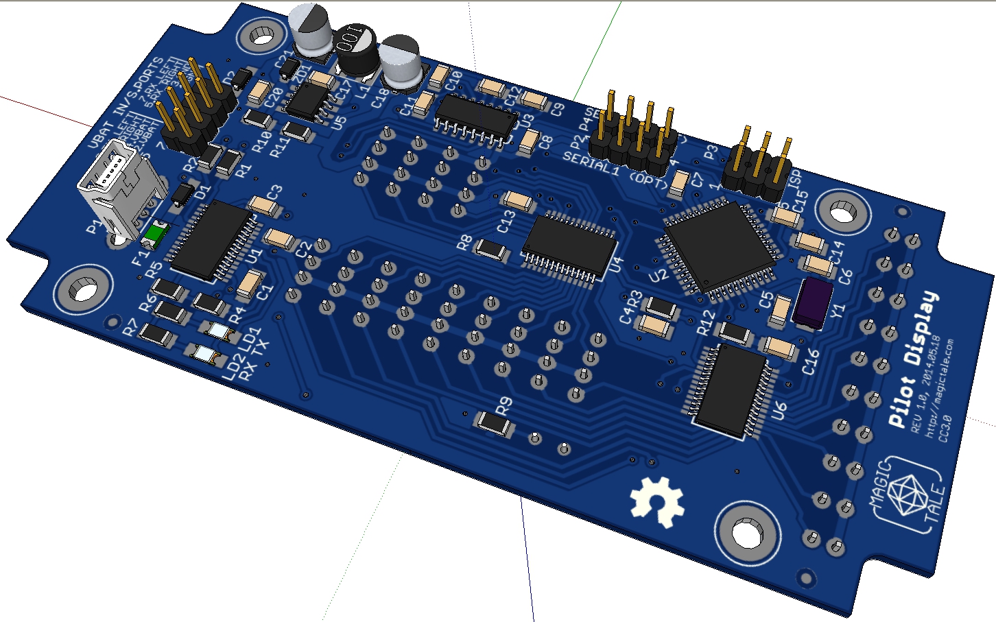
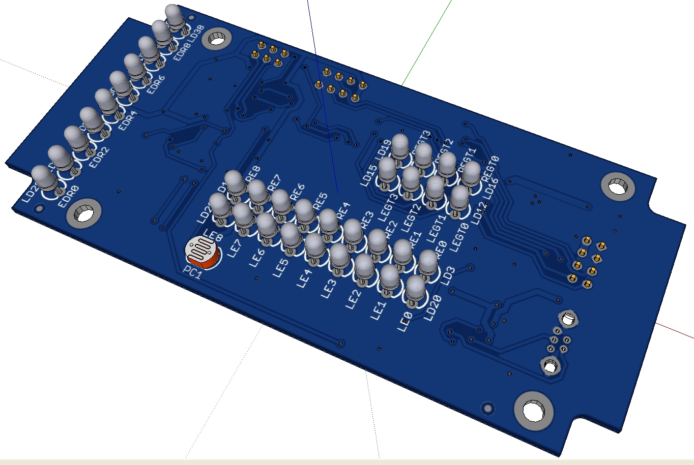
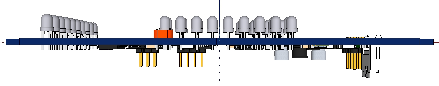
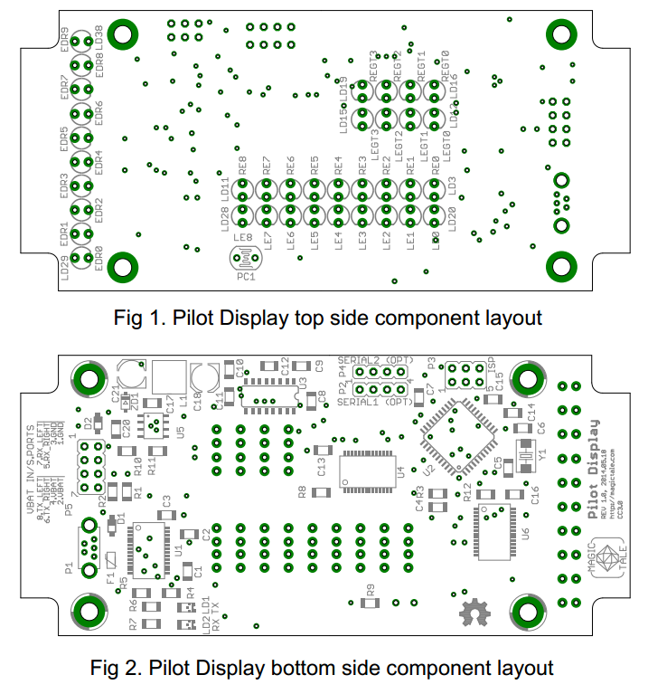 PilotDisplay Component Layout Rev1.0 A 3D model of the PCBA and Sketchup snapshots are given below.
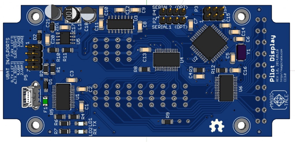 Pilot Display PCBA 3DModel Top View 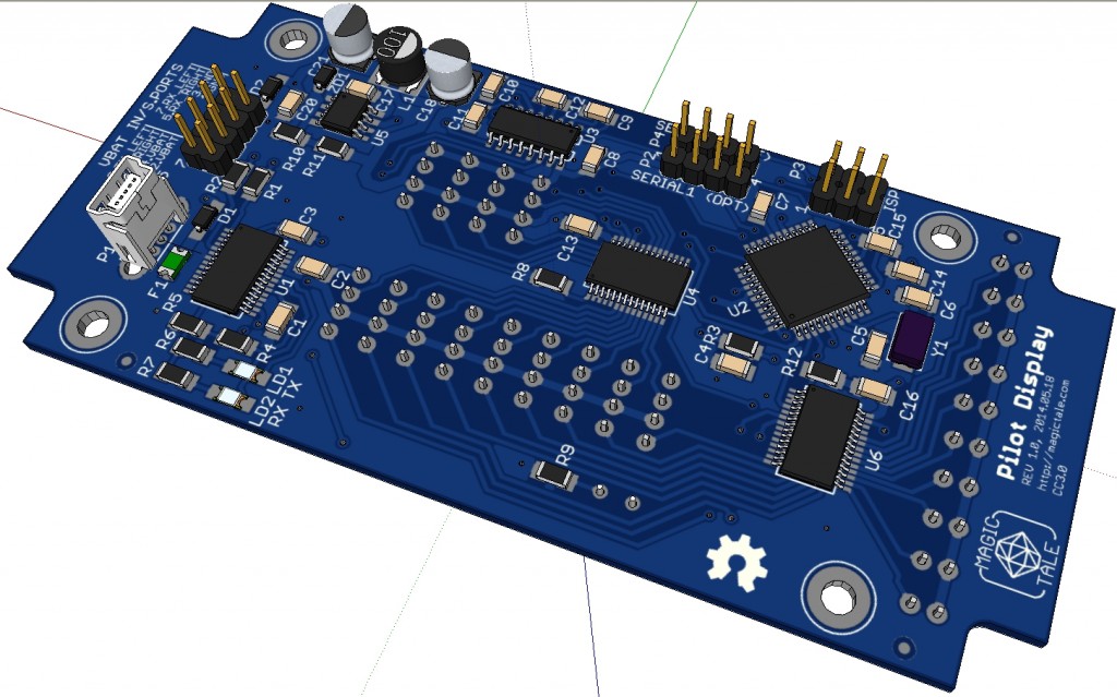 Pilot Display PCBA 3DModel Top ISO View  Pilot Display PCBA 3DModel Bottom ISO View  Pilot Display PCBA 3DModel Side View Downloads:
1. Pilot Display Gerber files Rev1.0
2. Pilot Display Eagle files Rev1.0
3. Pilot Display SketchUp 3D Model Rev1.0
4. Pilot Display Component 3D Models
5. Pilot Display BOM (Bill Of Materials)
Firmware source code is yet to come – stay tuned.
Knowing RFComm port number to connect to we are fully set for our final step – to establish RFComm communication channel. Before we can send RFComm specific commands we need to establish L2CAP connection to RFComm the same way as it has been already described in ‘Establishing connection to SDP’. The only difference is that this time we need to use RFComm PSM (0x03) rather than SDP PSM. Let’s not focus our attention on L2CAP as it is now a technicality of no interest and shift our attention to RFComm specifics.
Make the same preparations and run two consoles with logging hcpdump applications and it was described in this post. Let’s analyze packet exchange immediately after establishing connection to RFComm. Here is what the first console would typically report:
< ACL data: handle 43 flags 0x02 dlen 8
L2CAP(d): cid 0x0041 len 4 [psm 3]
RFCOMM(s): SABM: cr 1 dlci 0 pf 1 ilen 0 fcs 0x1c //1-st SABM command
> ACL data: handle 43 flags 0x02 dlen 8
L2CAP(d): cid 0x0041 len 4 [psm 3]
RFCOMM(s): UA: cr 1 dlci 0 pf 1 ilen 0 fcs 0xd7 //UA response

< ACL data: handle 43 flags 0x02 dlen 18
L2CAP(d): cid 0x0041 len 14 [psm 3]
RFCOMM(s): PN CMD: cr 1 dlci 0 pf 0 ilen 10 fcs 0x70 mcc_len 8 //PM (paramater negotiation) request
dlci 32 frame_type 0 credit_flow 15 pri 7 ack_timer 0
frame_size 55 max_retrans 0 credits 7
> ACL data: handle 43 flags 0x02 dlen 18
L2CAP(d): cid 0x0041 len 14 [psm 3]
RFCOMM(s): PN RSP: cr 0 dlci 0 pf 0 ilen 10 fcs 0xaa mcc_len 8 //PM (parameter negotiation) response
dlci 32 frame_type 0 credit_flow 14 pri 0 ack_timer 0
frame_size 55 max_retrans 0 credits 7

< ACL data: handle 43 flags 0x02 dlen 8
L2CAP(d): cid 0x0041 len 4 [psm 3]
RFCOMM(s): SABM: cr 1 dlci 32 pf 1 ilen 0 fcs 0xca //2-nd SAMB command
> ACL data: handle 43 flags 0x02 dlen 8
L2CAP(d): cid 0x0041 len 4 [psm 3]
RFCOMM(s): UA: cr 1 dlci 32 pf 1 ilen 0 fcs 0x1 //UA response

< ACL data: handle 43 flags 0x02 dlen 12
L2CAP(d): cid 0x0041 len 8 [psm 3]
RFCOMM(s): MSC CMD: cr 1 dlci 0 pf 0 ilen 4 fcs 0x70 mcc_len 2 //MSC (modem status) command
dlci 32 fc 0 rtc 1 rtr 1 ic 0 dv 1 b1 1 b2 1 b3 0 len 0
> ACL data: handle 43 flags 0x02 dlen 12
L2CAP(d): cid 0x0041 len 8 [psm 3]
RFCOMM(s): MSC CMD: cr 0 dlci 0 pf 0 ilen 4 fcs 0xaa mcc_len 2 //MSC (modem status) command
dlci 32 fc 0 rtc 1 rtr 1 ic 0 dv 1 b1 1 b2 1 b3 0 len 0

< ACL data: handle 43 flags 0x02 dlen 12
L2CAP(d): cid 0x0041 len 8 [psm 3]
RFCOMM(s): MSC RSP: cr 1 dlci 0 pf 0 ilen 4 fcs 0x70 mcc_len 2 //MSC (modem status) response
dlci 32 fc 0 rtc 1 rtr 1 ic 0 dv 1 b1 1 b2 1 b3 0 len 0
> ACL data: handle 43 flags 0x02 dlen 12
L2CAP(d): cid 0x0041 len 8 [psm 3]
RFCOMM(s): MSC RSP: cr 0 dlci 0 pf 0 ilen 4 fcs 0xaa mcc_len 2 //MSC (mode status) response
dlci 32 fc 0 rtc 1 rtr 1 ic 0 dv 1 b1 1 b2 1 b3 0 len 0

< ACL data: handle 43 flags 0x02 dlen 9
L2CAP(d): cid 0x0041 len 5 [psm 3]
RFCOMM(d): UIH: cr 1 dlci 32 pf 1 ilen 0 fcs 0xc4 credits 33 //Command with credit
Let’s have a look at the same exchange in raw representation logged by the second console and try to decode it:
< 0000: 02 2a 20 08 00 04 00 41  00 03 3f 01 1c           .* ....A..?.. //1-st SABM on channel 0 (byte @ 0x9 == 0x3)
> 0000: 02 2a 20 08 00 04 00 41  00 03 73 01 d7           .* ....A..s.. //UA response

< 0000: 02 2a 20 12 00 0e 00 41  00 03 ef 15 83 11 20 f0  .* ....A...... . //PM (paramater negotiation) request
0010: 07 00 37 00 00 07 70                              ..7...p
> 0000: 02 2a 20 12 00 0e 00 41  00 01 ef 15 81 11 20 e0  .* ....A...... . //PM (parameter negotiation) response
0010: 00 00 37 00 00 07 aa                              ..7....

< 0000: 02 2a 20 08 00 04 00 41  00 83 3f 01 ca           .* ....A..?.. //2-nd SABM  on channel 0x10 (byte @ 0x9 == 0x83, channel number << 3 = 0x80)
> 0000: 02 2a 20 08 00 04 00 41  00 83 73 01 01           .* ....A..s.. //UA response

< 0000: 02 2a 20 0c 00 08 00 41  00 03 ef 09 e3 05 83 8d  .* ....A........ //MSC (modem status) command
0010: 70                                                p
> 0000: 02 2a 20 0c 00 08 00 41  00 01 ef 09 e3 05 83 8d  .* ....A........ //MSC (modem status) command
0010: aa                                                .
< 0000: 02 2a 20 0c 00 08 00 41  00 03 ef 09 e1 05 83 8d  .* ....A........ //MSC (modem status) response
0010: 70                                                p
> 0000: 02 2a 20 0c 00 08 00 41  00 01 ef 09 e1 05 83 8d  .* ....A........ //MSC (modem status) response
0010: aa                                                .

< 0000: 02 2a 20 09 00 05 00 41  00 83 ff 01 21 c4        .* ....A....!. //Command with credit on channel 0x10

...and... rock'n'roll!
Time to put everything together. Get source code from Download section below, update your installation of USB Host 2.0 library on your machine, run the provided sketch making sure that ELM327 is powered and within range of your Luminardo board. You should see something similar to the output provided below. Note, that very last reply >LM327 v1.5 is transmitted by ELM327 which means that we have established SPP communication channel! The only remaining part now is to put logic which communicates with ELM327 and renders received values on VFD panel.
Luminardo USB Host Bluetooth SPP Test
SPP Bluetooth Library Started
Enabling VBus... enabled
Bluetooth Dongle Initialized
HCI Reset complete
Write class of device
Local Bluetooth Address: 00:19:0E:12:65:6A
The name is set to: Luminardo
Pairing to 'Other' device with predefined address
Device: 40:22:11:00:69:58 has been found
Connecting to 'Other' device...
Connected to 'Other' device
Received Key Request
Bluetooth pin is set too: 1234
Pairing successful with 'Other' device
SDP Connection Request Sent
L2CAP Connection Response
SDP Connection Response
SDP Configuration Request Received
SDP Configuration Response Sent
SDP Configuration Request Sent
SDP Configuration Response Received
SDP Successfully Configured
SDP Service Search Attribute Request 1 Sent
Channel will be in the next packet
SDP Service Search Attribute Request 2 Sent
Channel found in second packet: 16
RFComm Connection Request Sent
L2CAP Connection Response
RFComm Connection Response
RFComm Configuration Request Received
RFComm Configuration Response Sent
RFComm Configuration Request Sent
RFComm Configuration Response Received
RFComm Successfully Configured
RFComm SABM Sent
Received UA RFComm Packet on channel: 00
Sent UAH RFComm Cmd BT_RFCOMM_PN_CMD (Parameter Negotiation Request) on channel: 00
Received UIH RFComm Packet on channel: 00 - BT_RFCOMM_PN_RSP (Parameter Negotiation Response)
RFComm 2-nd SABM Sent
Received UA RFComm Packet on channel: 10
Send UIH RFComm Cmd BT_RFCOMM_MSC_CMD (Modem Status Command)
Received UIH RFComm Packet on channel: 00 - BT_RFCOMM_MSC_CMD (Modem Status Cmd)
Send UIH RFComm Cmd BT_RFCOMM_MSC_RSP (Modem Status Response)
Received UIH RFComm Packet on channel: 00 - BT_RFCOMM_MSC_RSP (Modem Status Response)
RFComm Cmd with Credit Sent
Serial Bluetooth connected

>LM327 v1.5
Now the implemented functionality allows to establish SPP communication between two Arduino boards equipped with USB Host shields. It is also quite remarkable that this particular Bluetooth dongle is not functional under WinXP because it comes with Win8 driver only yet our hardware happily communicates with the dongle!
Downloads:
1. USB Host 2.0 For Arduino – Bluetooth SPPi addon;
2. UPDATE 2014.09.28: Full snapshot of USB Host 2.0 For Arduino with Bluetooth SPPi addon;
As a result of effort in previous post we now armed with knowdledge what has to be done in order to connect to Bluetooth SDP (Service Discovery Protocol). All we need to get from SDP is a RFComm channel number to connect to, the rest information provided by SDP service while it is a subject of certain interest, not compulsory for our goal. Make the same preparations and run two consoles with logging hcpdump applications and it was described in the previous post. Let’s analyze packet exchange a bit further, immediately after establishing connection to SDP. Here is what the first console would typically report:
< ACL data: handle 43 flags 0x02 dlen 24
    L2CAP(d): cid 0x0040 len 20 [psm 1]
        SDP SSA Req: tid 0x0 len 0xf //Service search attribute request is sent to remote endpoint
          pat uuid-16 0x1101 (SP)
          max 65535
          aid(s) 0x0000 - 0xffff
          cont 00
> ACL data: handle 43 flags 0x02 dlen 50
    L2CAP(d): cid 0x0040 len 46 [psm 1]
        SDP SSA Rsp: tid 0x0 len 0x29 //Service search attribute response is received but it doesn't fit in one packet
          count 36
          cont 02 00 24 //Indication that there is still some data pending
< ACL data: handle 43 flags 0x02 dlen 26
    L2CAP(d): cid 0x0040 len 22 [psm 1]
        SDP SSA Req: tid 0x1 len 0x11 //Service search attribute request is sent again to fetch what didn't fit in the first packet
          pat uuid-16 0x1101 (SP)
          max 65535
          aid(s) 0x0000 - 0xffff
          cont 02 00 24 //Indication that we need to get the pending part of data
> ACL data: handle 43 flags 0x02 dlen 28
    L2CAP(d): cid 0x0040 len 24 [psm 1]
        SDP SSA Rsp: tid 0x1 len 0x13 //Second service search attribute response with remaining data
          count 16
          record #0
              aid 0x0000 (SrvRecHndl)
                 uint 0x10007
              aid 0x0001 (SrvClassIDList)
                 < uuid-16 0x1101 (SP) >
              aid 0x0004 (ProtocolDescList)
                 < < uuid-16 0x0100 (L2CAP) > <
                 uuid-16 0x0003 (RFCOMM) uint 0x10 > >
              aid 0x0009 (BTProfileDescList)
                 < < uuid-16 0x1101 (SP) uint 0x100 > >
          cont 00 //Indication that there is no pending data anymore
Let’s have a look at the same exchange in raw representation logged by the second console and try to decode it:
< 0000: 02 2a 20 18 00 14 00 40  00 06 00 00 00 0f 35 03  .* ....@......5. //1-st SDP_SERVICE_SEARCH_ATTRIBUTE_REQEUST_PDU (0x06 at address 0x0009)
  0010: 19 11 01 ff ff 35 05 0a  00 00 ff ff 00           .....5.......

> 0000: 02 2a 20 32 00 2e 00 40  00 07 00 00 00 29 00 24  .* 2...@.....).$ //1-st SDP_SERVICE_SEARCH_ATTRIBUTE_RESPONSE_PDU (0x07 at address 0x0009)
  0010: 36 00 31 36 00 2e 09 00  00 0a 00 01 00 07 09 00  6.16............
  0020: 01 35 03 19 11 01 09 00  04 35 0c 35 03 19 01 00  .5.......5.5....
  0030: 35 05 19 00 02 00 24                              5.....$

< 0000: 02 2a 20 1a 00 16 00 40  00 06 00 01 00 11 35 03  .* ....@......5. //1-st SDP_SERVICE_SEARCH_ATTRIBUTE_REQEUST_PDU (0x06 at address 0x0009)
  0010: 19 11 01 ff ff 35 05 0a  00 00 ff ff 02 00 24     .....5........$

> 0000: 02 2a 20 1c 00 18 00 40  00 07 00 01 00 13 00 10  .* ....@........ //2-nd SDP_SERVICE_SEARCH_ATTRIBUTE_RESPONSE_PDU (0x07 at address 0x0009)
  0010: 03 08 10 09 00 09 35 08  35 06 19 11 01 09 01 00  ......5.5.......
  0020: 00                                                .
Again, it would be worth getting familiar with internal packet structure and payload. An SDP service is basically a hierarchical list of attributes, each attribute has a list of field-value pairs and fields can have different types (byte, short, int – just like modern programming language). Attributes can be grouped and can nest more elements or groups inside. This is pretty much what we need to know about SDP services. Let’s have a closer look at the binary data:
=== HCI header ===
02 2a HCI hanle with PB and BC flags
20 18 HCI ACL total data length (it actually specifies total length 0x0018)
00 14 L2CAP payload length
00 40 SDP channel ID (please note that channel number is not 0x0001 anymore that is why the packet is interpreted as SDP_SERVICE_SEARCH_ATTRIBUTE_REQEUST_PDU
  and not as L2CAP_CMD_DISCONNECT_REQUEST (although they both have the same code)

00  ??? Unknown byte, it is present neither in spec nor in packets when sent from Arduino/Luminardo.
  Probably a bug in hcidump as the byte is not even accounted by HCI ACL total data length, just ignore it

=== Actual L2CAP command ===
06 SDP_SERVICE_SEARCH_ATTRIBUTE_REQEUST_PDU
00 00 Transaction identifier
00 0f Parameter length
{
  35 Data Element Sequence, data size in next 8 bits
  03 Data size
  {
    19 Field type UUID, 2 bytes
    11 01 Field value 0x0100 - L2CAP_UUID
  }
  ff ff Maximum attribute byte count
  35 Data Element Sequence, data size in next 8 bits
  05 Data size
  {
    0a Field type Unsigned int, 4 bytes  - Attribute ID range
    00 00 Attribute range from 0x0000...
    ff ff ... to 0xFFFF
  }
}
00 No more data
In essence, the packet above is requesting all attributes with identifiers from 0 to 0xFFFF from service with UUID = 0x0100.
=== HCI header ===
02 2a 20 32 00 2e 00 40  00 - HCI header, as above, please see the SDP_SERVICE_SEARCH_ATTRIBUTE_REQEUST_PDU packet structure

=== Actual L2CAP command ===
07 SDP_SERVICE_SEARCH_ATTRIBUTE_RESPONSE_PDU
00 00 Transaction identifier
00 29 Parameter length
00 24 Attribute lists byte count
{
  36 Data Element Sequence, size in next 16 bits
  00 31 Size
  {
    36 Data Element Sequence, size in next 16 bits
    00 2e Size
    {
      09 Unsigned integer in next 16 bits
      00 00 Attr ID 0000 - "Service Record Handle"
      0a Unsigned integer in next 32 bits
      00 01 00 07 Attr Value - handle

      09 Unsigned integer in next 16 bits
      00 01 Attr ID 0001 - "Service Class ID"
      35 Data Element Sequence, size in next 8 bits
      03 Size
      {
        19 UUID, 2 bytes
        11 01 "SERIALPORT  UUID"
      }

     09 Unsigned integer in next 16 bits
     00 04 Attr ID 0004 - "Protocol Descriptor List"
     35 Data Element Sequence, size in next 8 bits
     0c Size
     {
       35 Data Element Sequence, size in next 8 bits
       03 Size
       {
         19 UUID, 2 bytes
         01 00 "L2CAP UUID"
       }

       35 Data Element Sequence, size in next 8 bits
       05 Size
       {
         19 UUID, 2 bytes
         00 ... end of data, 3 bytes are still missing, will be continued in next package
         ...
       }
}
02 Size in next two bytes
00 24 More data to come
=== HCI header ===
02 2a 20 1a 00 16 00 40 00 - HCI header, as above, please see the SDP_SERVICE_SEARCH_ATTRIBUTE_REQEUST_PDU packet structure

=== Actual L2CAP command ===
06 SDP_SERVICE_SEARCH_ATTRIBUTE_REQEUST_PDU
00 01 Transaction Identifier
00 11 Parameter length
{
  35 Data Element Sequence, data size in next 8 bits
  03 Data Size
  {
    19 Field type UUID, 2 bytes
    11 01 Field value 0x0100 - L2CAP_UUID
  }
  ff ff Maximum attribute byte count
  35 Data Element Sequence, data size in next 8 bits
  05 Data Size
  {
    0a Field type Unsigned int, 4 bytes  - Attribute ID range
    00 00 Attribute range from 0x0000...
    ff ff ... to 0xFFFF
  }
}
02 Copied from last response,
00 24 in essence it is a request to get the remaining data
=== HCI header ===
02 2a 20 1c 00 18 00 40 00 - HCI header, as above, please see the SDP_SERVICE_SEARCH_ATTRIBUTE_REQEUST_PDU packet structure

=== Actual L2CAP command ===
07 SDP_SERVICE_SEARCH_ATTRIBUTE_RESPONSE_PDU
00 01 Transaction identifier
00 13 Parameter length
00 10 Attribute lists byte count
{
  03 Continuation of 0x00 from previous packet makes "00 03" - "RFCOMM UUID"
  08 Unsigned integer in next 8 bits
  10 Here it is, a RFComm channel number, that is what we are after!

  09 Unsigned integer in next 16 bits
  00 09 Attr ID 0009 - "Bluetooth Profile Descriptor List"
  35 Data Element Sequence, data size in next 8 bits
  08 Data Size
  {
    35 Data Element Sequence, data size in next 8 bits
    06 Data Size
    {
      19 UUID, 2 bytes
      11 01 "SERIALPORT  UUID"
      09 Unsigned int in next 16 bits
      01 00 Profile version number
   }
}
00 No more data
As an attentive reader has probably already noted, in the last package we received a value that we were after, it is RFComm channel number which is 0x10 for this particular case. At this point we know what has to be sent and how in order to get this magic number. Enough theories, time to put our knowledge in practice. As a prototype to validate our ideas with SDP service a limited in functionality class called SPPi has been designed, please refer to the Download section of this post. Copy SPPi.cpp and SPPi.h to USB Host 2.0 folder then compile and run Luminardo_USBHost_Bluetooth_SPPi.ino. The output should be like this (which proves that now we can talk SDP):
Luminardo USB Host Bluetooth SPPi Test
SPP Bluetooth Library Started
Enabling VBus... enabled
Bluetooth Dongle Initialized
HCI Reset complete
Write class of device
Local Bluetooth Address: 00:19:0E:12:65:6A
The name is set to: Luminardo
Pairing to 'Other' device with predefined address
Device: 40:22:11:00:69:58 has been found
Connecting to 'Other' device...
Connected to 'Other' device
Received Key Request
Bluetooth pin is set too: 1234
Pairing successful with 'Other' device
SDP Connection Request
L2CAP Connection Response
SDP Connection Response
SDP Configuration Request Received
SDP Configuration Response Sent
SDP Configuration Request Sent
SDP Configuration Response Received
SDP Successfully Configured
SDP Service Search Attribute Request 1 Sent
SDP data... - SDP Service Search Attribute Response 1: 0B 20 34 00 30 00 41 00 07 00 48 00 2B 00 26 36 00 31 36 00 2E 09 00 00 0A 00 01 00 07 09 00 01 35 03 19
11 01 09 00 04 35 0C 35 03 19 01 00 35 05 19 00 03 08 02 00 26
SDP Service Search Attribute Request 2 Sent
SDP data... - SDP Service Search Attribute Response 2: 0B 20 1A 00 16 00 41 00 07 00 49 00 11 00 0E 10 09 00 09 35 08 35 06 19 11 01 09 01 00 00
Now you can move to the next, final step – to start RFComm transport layer which will be described in detail in next post. Stay tuned and don’t hesitate to ask questions!
Downloads:
1. USB Host 2.0 Add-on Allowing to Initiate Communication with SDP service.
This post is a continuation of our endeavour to enhance USB Host 2.0 for Arduino library making a particular focus on SPP Bluetooth profile and Luminardo’s ability to initiate connection to a remote Bluetooth SPP-aware hardware. Last time it has been described what had to be changed in the library in order for Luminardo to start pairing sequence. Today we are going to progress further and discover what else has to be done. But before we proceed first we need do to some preparations to make sure that we have tools and documentation handy. Note, that this post doesn’t set a goal to make a complete Bluetooth guide, it is rather an example which demostrates where to start and how to learn in order to solve a problem related to BT stack.
First of all, we would need Bluetooth core specification. It sounds obvious but strangely enough it is not such as straightforward as it seems: there are several core specifications with version numbers ranging from 2.0 to 4.1 not to mention numerous specification ‘addendums’. A brief investigation reveals that the library is built around rev.4.0 and the appropriate document location would be here. Two more documents would be also extremely useful: SPP Specification ver.1.2 and GSM 07.10 Specification.
Secondly, having a real working system (e.g. two Bluetooth SPP-aware devices) as a reference point can significantly simplify the learning process as all the above mentioned documents are really difficult to read and even more difficult to comprehend. Being able to watch the actual data exchange is a must. Using a PC with Windows OS gives virtually nothing as the Bluetooth stack is an integral part of OS kernel and apparently there is no way to sniff or log Bluetooth packets. What is even worse, different versions of Windows use completely different Bluetooth stacks but all of them are black boxes – nobody knows what is happening inside. On the other hand, Linux and its Bluetooth stack have everything in place for efficient packet debuging and troubleshooting. Out team used Lubuntu with pre-installed Bluez package. Hovewer, to log packets one more package must be installed: bluez-hcidump. In our environment all that needed to be done to install it was apt-get install bluez-hcidump in command line.
And finally we would need a device to connect to. It could be another PC or laptor with Bluetooth adapter or an ELM327 adapter. In latter case an adapter must be powered up as at this stage there is no need in physical communication with car’s bus and it is enough to apply supply voltage only. Also it is extremely inconvenient to run experiments in a car be it inside a dark garage or a parking spot, a home lab would be a better place. Any 12VDC power supply capable of delivering at least 100 mA will do. During our tests we used a bench power supply as shown on the pictures below. Make sure you get polarity right: brown wire is GND, red wire is +12VDC.
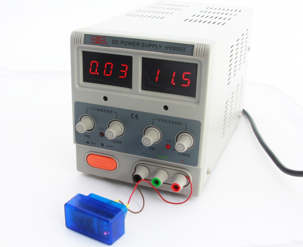 Powering ELM327 off Bench Power Supply 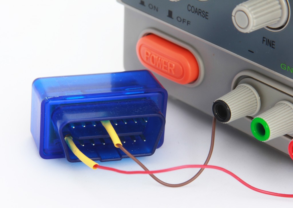 Powering ELM327: wiring polarity Now a significant amount of time must be spent trying to combine knowledge contained in Bluetooth specs, logic contained in SPP.cpp and BTD.cpp files and common sense. It also takes some time to get familiar with bluez-hcidump peculiarities as it offers wide range of options allowing to log in different formats. The specs are written in a very strange way, while reading you keep asking yourself only one question over and over again: what were those guys smoking when they wrote those specs? Information is scattered across not only pages and chapters but different files as well, it is extremely difficult to make sense out of it. They keep jumping from one topic to another, often using lengthy descriptions of an entity or a process while a single picture-example would be worth a thousand words, you need to read the same passage multiple times trying to understand what they meant. What is even worse, the information often looks ambiguous and inconclusive, there is no way to comprehend it fully unless you have a real hardware and library to conduct some experiments to proof or disproof your guesses after reading the spec. The information available in the Internet is surprisingly scarce: apart from the official Bluetooth specs which are easy to understand only for people who wrote them there is basically nothing else. Documentation and forum discussions for Bluez or btstack are only about API and how to use it, the actual implementations of the stacks are not discussed as such or discussed by BT professionals who already has a deep knowledge of the specifications. It looks like everyone considers the stack as a given without actual understanding how and why it works, and those who know about it prefer to keep the knowledge closed, it is really unclear how overcome this vacuum before you know enough to progress further towards the numbered group of Bluetooth guru.
As we already spent significant amount of time here are some facts that came out of our effort:
1. Reversing the role of our device from acceptor to initiator requires rater major redesign of logic resided in SPP.cpp. Format and content of packets sent by initiator is unknown at the moment and yet to be discovered;
2. In order to establish connection to a remote device via SPP it is required to interrogate SDP service to get a port number to connect to;
3. As soon as port number is known, connection to RFComm service should be initiated.
All interactions with SDP and RFComm services are done trough underlying L2CAP interface, for simplicity sake consider it as a backbone transport layer. Before any requests can be sent to either SDP or RFComm services a connection to that service has to be established by means of standard set of L2CAP commands. The order of these commands is important. In most cases if a command is malformed or sent at inappropriate time it will be ignored and no error packet of any kind will be sent which undoubtedly makes troubleshooting more difficult. A typical sequence of establishing connection to an SDP (RFComm or any other) service is given below:
1. Initiator sends CONNECTION REQUEST;
2. Acceptor replies with CONNECTION RESPONSE and shortly after sends CONFIGURATION REQUEST;
3. Initiator replies with CONFIGURATION RESPONSE and shortly after sends CONFIGURATION REQUEST (or the other way around);
4. Acceptor replies with CONFIGURATION RESPONSE – and from this moment connection is established and service specific commands can be sent;
Let’s confirm our theoretical knowledge with real working system. Power up ELM327 then start Bluetooth Manager in Linux, search for available devices and it should detect ELM327 as ‘OBDII’. Pair with it and enter pin ‘1234’ when requested (please refer to user manual of your ELM327 as there could be another value for pin code). Start Linux two consoles and run in first one hcidump command without parameters and in second one hcidump - X -R command. Then go to OBDII’s properties, click ‘Setup’ and select ‘Connect to Serial Port’. You should see data coming in and out logged by hcidump. Here is a portion of data logged by the first console:
< ACL data: handle 43 flags 0x02 dlen 12
    L2CAP(s): Connect req: psm 1 scid 0x0040  //outgoing CONNECTION REQUEST to PSM = 1 (Service Discovery Protocol) from a client with SCID = 0x0040 (Source Channel Identifier, a unique ID of our endpoint or client)
> ACL data: handle 43 flags 0x02 dlen 16
    L2CAP(s): Connect rsp: dcid 0x0040 scid 0x0040 result 0 status 0 //incoming CONNECTION RESPONSE from a remote endpoint with DCID = 0x0040 with result and status set to 0 (success)
      Connection successful
< ACL data: handle 43 flags 0x02 dlen 12
    L2CAP(s): Config req: dcid 0x0040 flags 0x00 clen 0 //outgoing CONFIG REQUEST from our endpoint with config parameters (flags) set to 0
> ACL data: handle 43 flags 0x02 dlen 20
    L2CAP(s): Config req: dcid 0x0040 flags 0x00 clen 8 //incoming CONFIG REQUEST from remote endpoint
      MTU 60
      FlushTO 65535
< ACL data: handle 43 flags 0x02 dlen 18
    L2CAP(s): Config rsp: scid 0x0040 flags 0x00 result 0 clen 4 //outgoing CONFIG RESPONSE from our endpoint
      MTU 60
> ACL data: handle 43 flags 0x02 dlen 18
    L2CAP(s): Config rsp: scid 0x0040 flags 0x00 result 0 clen 4 //incoming CONFIG RESPONSE from remote endpoint
      MTU 48
The second console logs data in raw format and gives opportunity to see actual byte stream. The same portion of data will look like this:
< 0000: 02 2a 20 0c 00 08 00 01  00 02 03 04 00 01 00 40  .* ............@ //outgoing L2CAP CMD CONNECTION REQUEST (0x02 at address 0x0009)
  0010: 00                                                .

> 0000: 02 2a 20 10 00 0c 00 01  00 03 03 08 00 40 00 40  .* ..........@.@ //incoming L2CAP CMD CONNECTION RESPONSE (0x03 at address 0x0009)
  0010: 00 00 00 00 00                                    .....

< 0000: 02 2a 20 0c 00 08 00 01  00 04 04 04 00 40 00 00  .* ..........@.. //outgoing L2CAP CONFIG REQUEST (0x04 at address 0x0009)
  0010: 00                                                .

> 0000: 02 2a 20 14 00 10 00 01  00 04 4c 0c 00 40 00 00  .* .......L..@.. //incoming L2CAP CONFIG REQUEST (0x04 at address 0x0009)
  0010: 00 01 02 3c 00 02 02 ff  ff                       ...<.....

< 0000: 02 2a 20 12 00 0e 00 01  00 05 4c 0a 00 40 00 00  .* .......L..@.. //outgoing L2CAP CONFIG RESPONSE (0x05 at address 0x0009)
  0010: 00 00 00 01 02 3c 00                              .....<.

> 0000: 02 2a 20 12 00 0e 00 01  00 05 04 0a 00 40 00 00  .* ..........@.. //incoming L2CAP CONFIG RESPONSE (0x05 at address 0x0009)
  0010: 00 00 00 01 02 30 00                              .....0.
At this stage it would be worth to get familiar a bit with packet structure and payload. So far there are four packet types: L2CAP CONNECTION REQUEST, L2CAP CONNECTION RESPONSE, L2CAP CONFIG REQUEST and L2CAP CONFIG RESPONSE. All four structures are given below.
=== HCI header ===
02 2a HCI hanle with PB and BC flags
20 0c HCI ACL total data length (it actually specifies total length 0x000C
   according to Bluetooth Core Spec. rev.4.0, Host Controller Interface Functional Spec)
   and be 0C 00 instead of 20 0C but we don't worry about it now - it works for us anyway
00 08 L2CAP payload length
00 01 L2CAP channel ID (0x0001 for ACL-U, please refer to Bluetooth Core Spec. rev.4.0,
  Logical Link Control and Adaptation Protocol Specification, page 54)

00 ??? Unknown byte, it is present neither in spec nor in packets when sent from Arduino/Luminardo.
  Probably a bug in hcidump as the byte is not even accounted by HCI ACL total data length

=== Actual L2CAP command ===
02 L2CAP_CMD_CONNECTION_REQUEST
03 Packet identifier
04 00 Command payload Length
01 00 SDP_PSM
40 00 SCID, Source Channel Identifier
=== HCI header ===
02 2a 20 10 00 0c 00 01  00 - HCI header, as above, please see the L2CAP CONNECTION REQUEST packet structure

=== Actual L2CAP command ===
03 L2CAP_CMD_CONNECTION_RESPONSE
03 Packet identifier
08 00 Command payload length
40 00 DCID (Destination Channel Identifier, in other words, a remote endpoint ID)
40 00 SCID (Source Channel Identifier, in other words, local endpoint ID)
00 00 Result 0 (success)
00 00 No more data
1-st case in our log generated by sniffer
=== HCI header ===
02 2a 20 0c 00 08 00 01 00 - HCI header, as above, please see the L2CAP CONNECTION REQUEST packet structure

=== Actual L2CAP command ===
04 L2CAP_CMD_CONFIG_REQUEST
04 Packet identifier
04 00 Command payload length
40 00 DCID (Destination Channel Identifier, in other words, a remote endpoint ID)
00 00 Flags


2-nd case in our log generated by sniffer
=== HCI header ===
02 2a 20 14 00 10 00 01 00 - HCI header, as above, please see the L2CAP CONNECTION REQUEST packet structure

=== Actual L2CAP command ===
04 L2CAP_CMD_CONFIG_REQUEST
4c Packet identifier
0c 00 Command payload length
40 00 DCID (Destination Channel Identifier, in other words, a remote endpoint ID)
00 00 Flags
01 Config Opt: type = MTU (Maximum Transmission Unit) - Hint
02 Config Opt: length
3c 00 MTU
02 Config Opt: type = Flush Timeout
02 Config Opt: length
ff ff Flush timeout
=== HCI header ===
02 2a 20 12 00 0e 00 01 00 - HCI header, as above, please see the L2CAP CONNECTION REQUEST packet structure

=== Actual L2CAP command ===
05 L2CAP_CMD_CONFIG_RESPONSE
4c Packet identifier
0a 00 Command payload length
40 00 SCID (Source Channel Identifier, in other words, local endpoint ID)
00 00 Flag 0
00 00 Result 0 (success)
01 Config Opt: type = MTU (Maximum Transmission Unit) - Hint
02 Config Opt: length
3c 00 MTU
Now we have a bit of understanding on how to establish connection to SDP service (same applies to RFCom) and we are ready to comminicate with SDP service. What should be done and how to do it will be discussed in our nest post. Stay tuned and ask questions if you have any!
Our next goal would be to establish communication between Luminardo and ELM327 OBDII Bluetooth adapter like the one shown on the picture below. The adapter allows not to interfere with wires and therefore eliminates (or at least minimises) chances of running into problems with car’s onboard electronics, however, Bluetooth link adds up an additional complexity which becomes extra burden on our shoulders. ELM327 operates wirelessly via Bluetooth link using so-called SPP interface – a Serial Port Profile which is based on ETSI 07.10 and the RFCOMM protocols effectively eliminating need for physical wires yet logically representing the well-known RS232 serial interface. It doesn’t sound particulary scary especially taking into account that USB Host 2.0 for Arduino library has an extensive support for Bluetooth profiles and SPP is one of them. However, don’t get carried away as the sketch that demonstrates usage of SPP stack won’t work for our case. To get to know why please keep reading this post.
 Mini ELM327 Bluetooth OBDII Adapter There is a fundamental difference between Bluetooth devices which INITIATE connection and the ones which ACCEPT connection. Most bluetooth profiles which are currently part of USB Host 2.0 for Arduino are built as ACCEPTORS, in other words, it is Arduino board which waits for a Bluetooth-enabled device to initiate connection and establish communication. There are two exceptions, HID and Wii devices which work the other way around, however, it is not the case for SPP profile which is the subject of our particular interest. So our Luminardo won’t make an effort of starting a connection for SPP profile. Needless to say that ELM327 would do the same, it only waits for incomming connections and does not have any intention to take the initiative. The irony of this situation is highlighted by that simple fact that currenly there is no way to make two Arduino boards talking over SPP and our task would be to implement the lacking functionality.
Without falling into lengthy explanations about Bluetooth specification we just would note for now that in order to initiate connection to a remote SPP-aware device the following three steps must be done: 1) initiate and complete Bluetooth pairing, 2) connect to and inquire a remote SDP (Service discovery protocol) service to get parameters for establishing RFComm transport layer and 3) establish connection to RFComm. Right now we will make an effort to take the first step only. First of all, we need to enhance BTD.h and BTH.cpp in such a way that we would be able to specify whether Luminardo should initiate or accept pairing procedure. The modified BTD.h is given below (please scroll down and refer to the highlighted lines):
/* Copyright (C) 2012 Kristian Lauszus, TKJ Electronics. All rights reserved.

This software may be distributed and modified under the terms of the GNU
General Public License version 2 (GPL2) as published by the Free Software
Foundation and appearing in the file GPL2.TXT included in the packaging of
this file. Please note that GPL2 Section 2[b] requires that all works based
on this software must also be made publicly available under the terms of
the GPL2 ("Copyleft").

Contact information
-------------------

Kristian Lauszus, TKJ Electronics
Web      :  http://www.tkjelectronics.com
e-mail   :  kristianl@tkjelectronics.com
*/

#ifndef _btd_h_
#define _btd_h_

#include "Usb.h"

//PID and VID of the Sony PS3 devices
#define PS3_VID                 0x054C  // Sony Corporation
#define PS3_PID                 0x0268  // PS3 Controller DualShock 3
#define PS3NAVIGATION_PID       0x042F  // Navigation controller
#define PS3MOVE_PID             0x03D5  // Motion controller

#define IOGEAR_GBU521_VID       0x0A5C // The IOGEAR GBU521 dongle does not presents itself correctly, so we have to check for it manually
#define IOGEAR_GBU521_PID       0x21E8

/* Bluetooth dongle data taken from descriptors */
#define BULK_MAXPKTSIZE         64 // Max size for ACL data

// Used in control endpoint header for HCI Commands
#define bmREQ_HCI_OUT USB_SETUP_HOST_TO_DEVICE|USB_SETUP_TYPE_CLASS|USB_SETUP_RECIPIENT_DEVICE
// Used in control endpoint header for HID Commands
#define bmREQ_HID_OUT USB_SETUP_HOST_TO_DEVICE|USB_SETUP_TYPE_CLASS|USB_SETUP_RECIPIENT_INTERFACE
#define HID_REQUEST_SET_REPORT      0x09

/* Bluetooth HCI states for hci_task() */
#define HCI_INIT_STATE                  0
#define HCI_RESET_STATE                 1
#define HCI_CLASS_STATE                 2
#define HCI_BDADDR_STATE                3
#define HCI_LOCAL_VERSION_STATE         4
#define HCI_SET_NAME_STATE              5
#define HCI_CHECK_DEVICE_SERVICE        6

#define HCI_INQUIRY_STATE               7 // These three states are only used if it should pair and connect to a device
#define HCI_CONNECT_DEVICE_STATE        8
#define HCI_CONNECTED_DEVICE_STATE      9

#define HCI_SCANNING_STATE              10
#define HCI_CONNECT_IN_STATE            11
#define HCI_REMOTE_NAME_STATE           12
#define HCI_CONNECTED_STATE             13
#define HCI_DISABLE_SCAN_STATE          14
#define HCI_DONE_STATE                  15
#define HCI_DISCONNECT_STATE            16

/* HCI event flags*/
#define HCI_FLAG_CMD_COMPLETE           0x01
#define HCI_FLAG_CONNECT_COMPLETE       0x02
#define HCI_FLAG_DISCONNECT_COMPLETE    0x04
#define HCI_FLAG_REMOTE_NAME_COMPLETE   0x08
#define HCI_FLAG_INCOMING_REQUEST       0x10
#define HCI_FLAG_READ_BDADDR            0x20
#define HCI_FLAG_READ_VERSION           0x40
#define HCI_FLAG_DEVICE_FOUND           0x80
#define HCI_FLAG_CONNECT_EVENT          0x100

/* Macros for HCI event flag tests */
#define hci_check_flag(flag) (hci_event_flag & (flag))
#define hci_set_flag(flag) (hci_event_flag |= (flag))
#define hci_clear_flag(flag) (hci_event_flag &= ~(flag))

/* HCI Events managed */
#define EV_INQUIRY_COMPLETE                             0x01
#define EV_INQUIRY_RESULT                               0x02
#define EV_CONNECT_COMPLETE                             0x03
#define EV_INCOMING_CONNECT                             0x04
#define EV_DISCONNECT_COMPLETE                          0x05
#define EV_AUTHENTICATION_COMPLETE                      0x06
#define EV_REMOTE_NAME_COMPLETE                         0x07
#define EV_ENCRYPTION_CHANGE                            0x08
#define EV_CHANGE_CONNECTION_LINK                       0x09
#define EV_ROLE_CHANGED                                 0x12
#define EV_NUM_COMPLETE_PKT                             0x13
#define EV_PIN_CODE_REQUEST                             0x16
#define EV_LINK_KEY_REQUEST                             0x17
#define EV_LINK_KEY_NOTIFICATION                        0x18
#define EV_DATA_BUFFER_OVERFLOW                         0x1A
#define EV_MAX_SLOTS_CHANGE                             0x1B
#define EV_READ_REMOTE_VERSION_INFORMATION_COMPLETE     0x0C
#define EV_QOS_SETUP_COMPLETE                           0x0D
#define EV_COMMAND_COMPLETE                             0x0E
#define EV_COMMAND_STATUS                               0x0F
#define EV_LOOPBACK_COMMAND                             0x19
#define EV_PAGE_SCAN_REP_MODE                           0x20

/* Bluetooth states for the different Bluetooth drivers */
#define L2CAP_WAIT                      0
#define L2CAP_DONE                      1

/* Used for HID Control channel */
#define L2CAP_CONTROL_CONNECT_REQUEST   2
#define L2CAP_CONTROL_CONFIG_REQUEST    3
#define L2CAP_CONTROL_SUCCESS           4
#define L2CAP_CONTROL_DISCONNECT        5

/* Used for HID Interrupt channel */
#define L2CAP_INTERRUPT_SETUP           6
#define L2CAP_INTERRUPT_CONNECT_REQUEST 7
#define L2CAP_INTERRUPT_CONFIG_REQUEST  8
#define L2CAP_INTERRUPT_DISCONNECT      9

/* Used for SDP channel */
#define L2CAP_SDP_WAIT                  10
#define L2CAP_SDP_SUCCESS               11

/* Used for RFCOMM channel */
#define L2CAP_RFCOMM_WAIT               12
#define L2CAP_RFCOMM_SUCCESS            13

#define L2CAP_DISCONNECT_RESPONSE       14 // Used for both SDP and RFCOMM channel

/* Bluetooth states used by some drivers */
#define TURN_ON_LED                     17
#define PS3_ENABLE_SIXAXIS              18
#define WII_CHECK_MOTION_PLUS_STATE     19
#define WII_CHECK_EXTENSION_STATE       20
#define WII_INIT_MOTION_PLUS_STATE      21

/* L2CAP event flags for HID Control channel */
#define L2CAP_FLAG_CONNECTION_CONTROL_REQUEST           0x00000001
#define L2CAP_FLAG_CONFIG_CONTROL_SUCCESS               0x00000002
#define L2CAP_FLAG_CONTROL_CONNECTED                    0x00000004
#define L2CAP_FLAG_DISCONNECT_CONTROL_RESPONSE          0x00000008

/* L2CAP event flags for HID Interrupt channel */
#define L2CAP_FLAG_CONNECTION_INTERRUPT_REQUEST         0x00000010
#define L2CAP_FLAG_CONFIG_INTERRUPT_SUCCESS             0x00000020
#define L2CAP_FLAG_INTERRUPT_CONNECTED                  0x00000040
#define L2CAP_FLAG_DISCONNECT_INTERRUPT_RESPONSE        0x00000080

/* L2CAP event flags for SDP channel */
#define L2CAP_FLAG_CONNECTION_SDP_REQUEST               0x00000100
#define L2CAP_FLAG_CONFIG_SDP_SUCCESS                   0x00000200
#define L2CAP_FLAG_DISCONNECT_SDP_REQUEST               0x00000400

/* L2CAP event flags for RFCOMM channel */
#define L2CAP_FLAG_CONNECTION_RFCOMM_REQUEST            0x00000800
#define L2CAP_FLAG_CONFIG_RFCOMM_SUCCESS                0x00001000
#define L2CAP_FLAG_DISCONNECT_RFCOMM_REQUEST            0x00002000

#define L2CAP_FLAG_DISCONNECT_RESPONSE                  0x00004000

/* Macros for L2CAP event flag tests */
#define l2cap_check_flag(flag) (l2cap_event_flag & (flag))
#define l2cap_set_flag(flag) (l2cap_event_flag |= (flag))
#define l2cap_clear_flag(flag) (l2cap_event_flag &= ~(flag))

/* L2CAP signaling commands */
#define L2CAP_CMD_COMMAND_REJECT        0x01
#define L2CAP_CMD_CONNECTION_REQUEST    0x02
#define L2CAP_CMD_CONNECTION_RESPONSE   0x03
#define L2CAP_CMD_CONFIG_REQUEST        0x04
#define L2CAP_CMD_CONFIG_RESPONSE       0x05
#define L2CAP_CMD_DISCONNECT_REQUEST    0x06
#define L2CAP_CMD_DISCONNECT_RESPONSE   0x07
#define L2CAP_CMD_INFORMATION_REQUEST   0x0A
#define L2CAP_CMD_INFORMATION_RESPONSE  0x0B

// Used For Connection Response - Remember to Include High Byte
#define PENDING     0x01
#define SUCCESSFUL  0x00

/* Bluetooth L2CAP PSM - see http://www.bluetooth.org/Technical/AssignedNumbers/logical_link.htm */
#define SDP_PSM         0x01 // Service Discovery Protocol PSM Value
#define RFCOMM_PSM      0x03 // RFCOMM PSM Value
#define HID_CTRL_PSM    0x11 // HID_Control PSM Value
#define HID_INTR_PSM    0x13 // HID_Interrupt PSM Value

// Used to determine if it is a Bluetooth dongle
#define WI_SUBCLASS_RF      0x01 // RF Controller
#define WI_PROTOCOL_BT      0x01 // Bluetooth Programming Interface

#define BTD_MAX_ENDPOINTS   4
#define BTD_NUM_SERVICES    4 // Max number of Bluetooth services - if you need more than 4 simply increase this number

#define PAIR    1

/* acl_handle_ok or it's a new connection */
#if 0
#define UHS_ACL_HANDLE_OK(x, y) ((uint16_t)(x[0]) | (uint16_t)(x[1] << 8)) == (y | 0x2000U)
#else
/*
*  Better implementation.
*  o One place for this code, it is reused four times in the source.
*    Perhaps it is better as a function.
*  o This should be faster since the && operation can early exit, this means
*    the shift would only be performed if the first byte matches.
*  o Casting is eliminated.
*  o How does this compare in code size? No difference. It is a free optimization.
*/
#define UHS_ACL_HANDLE_OK(x, y) ((x[0] == (y & 0xff)) && (x[1] == ((y >> 8) | 0x20)))
#endif

/** All Bluetooth services should inherit this class. */
class BluetoothService {
public:
/**
* Used to pass acldata to the Bluetooth service.
* @param ACLData Pointer to the incoming acldata.
*/
virtual void ACLData(uint8_t* ACLData);
/** Used to run the different state machines in the Bluetooth service. */
virtual void Run();
/** Used to reset the Bluetooth service. */
virtual void Reset();
/** Used to disconnect both the L2CAP Channel and the HCI Connection for the Bluetooth service. */
virtual void disconnect();
};

/**
* The Bluetooth Dongle class will take care of all the USB communication
* and then pass the data to the BluetoothService classes.
*/
class BTD : public USBDeviceConfig, public UsbConfigXtracter {
public:
/**
* Constructor for the BTD class.
* @param  p   Pointer to USB class instance.
*/
BTD(USB *p);

/** @name USBDeviceConfig implementation */
/**
* Address assignment and basic initialization is done here.
* @param  parent   Hub number.
* @param  port     Port number on the hub.
* @param  lowspeed Speed of the device.
* @return          0 on success.
*/
virtual uint8_t ConfigureDevice(uint8_t parent, uint8_t port, bool lowspeed);
/**
* Initialize the Bluetooth dongle.
* @param  parent   Hub number.
* @param  port     Port number on the hub.
* @param  lowspeed Speed of the device.
* @return          0 on success.
*/
virtual uint8_t Init(uint8_t parent, uint8_t port, bool lowspeed);
/**
* Release the USB device.
* @return 0 on success.
*/
virtual uint8_t Release();
/**
* Poll the USB Input endpoints and run the state machines.
* @return 0 on success.
*/
virtual uint8_t Poll();

/**
* Get the device address.
* @return The device address.
*/
virtual uint8_t GetAddress() {
return bAddress;
};

/**
* Used to check if the dongle has been initialized.
* @return True if it's ready.
*/
virtual bool isReady() {
return bPollEnable;
};

/**
* Used by the USB core to check what this driver support.
* @param  klass The device's USB class.
* @return       Returns true if the device's USB class matches this driver.
*/
virtual boolean DEVCLASSOK(uint8_t klass) {
return (klass == USB_CLASS_WIRELESS_CTRL);
};

/**
* Used by the USB core to check what this driver support.
* Used to set the Bluetooth address into the PS3 controllers.
* @param  vid The device's VID.
* @param  pid The device's PID.
* @return     Returns true if the device's VID and PID matches this driver.
*/
virtual boolean VIDPIDOK(uint16_t vid, uint16_t pid) {
if(vid == IOGEAR_GBU521_VID && pid == IOGEAR_GBU521_PID)
return true;
if(my_bdaddr[0] != 0x00 || my_bdaddr[1] != 0x00 || my_bdaddr[2] != 0x00 || my_bdaddr[3] != 0x00 || my_bdaddr[4] != 0x00 || my_bdaddr[5] != 0x00) { // Check if Bluetooth address is set
if(vid == PS3_VID && (pid == PS3_PID || pid == PS3NAVIGATION_PID || pid == PS3MOVE_PID))
return true;
}
return false;
};
/**@}*/

/** @name UsbConfigXtracter implementation */
/**
* UsbConfigXtracter implementation, used to extract endpoint information.
* @param conf  Configuration value.
* @param iface Interface number.
* @param alt   Alternate setting.
* @param proto Interface Protocol.
* @param ep    Endpoint Descriptor.
*/
virtual void EndpointXtract(uint8_t conf, uint8_t iface, uint8_t alt, uint8_t proto, const USB_ENDPOINT_DESCRIPTOR *ep);
/**@}*/

/** Disconnects both the L2CAP Channel and the HCI Connection for all Bluetooth services. */
void disconnect() {
for(uint8_t i = 0; i < BTD_NUM_SERVICES; i++)
if(btService[i])
btService[i]->disconnect();
};

/**
* Register Bluetooth dongle members/services.
* @param  pService Pointer to BluetoothService class instance.
* @return          The service ID on success or -1 on fail.
*/
int8_t registerServiceClass(BluetoothService *pService) {
for(uint8_t i = 0; i < BTD_NUM_SERVICES; i++) {
if(!btService[i]) {
btService[i] = pService;
return i; // Return ID
}
}
return -1; // ErrorregisterServiceClass
};

/** @name HCI Commands */
/**
* Used to send a HCI Command.
* @param data   Data to send.
* @param nbytes Number of bytes to send.
*/
void HCI_Command(uint8_t* data, uint16_t nbytes);
/** Reset the Bluetooth dongle. */
void hci_reset();
/** Read the Bluetooth address of the dongle. */
void hci_read_bdaddr();
/** Read the HCI Version of the Bluetooth dongle. */
void hci_read_local_version_information();
/**
* Set the local name of the Bluetooth dongle.
* @param name Desired name.
*/
void hci_set_local_name(const char* name);
/** Enable visibility to other Bluetooth devices. */
void hci_write_scan_enable();
/** Disable visibility to other Bluetooth devices. */
void hci_write_scan_disable();
/** Read the remote devices name. */
void hci_remote_name();
/** Accept the connection with the Bluetooth device. */
void hci_accept_connection();
/**
* Disconnect the HCI connection.
* @param handle The HCI Handle for the connection.
*/
void hci_disconnect(uint16_t handle);
/**
* Respond with the pin for the connection.
* The pin is automatically set for the Wii library,
* but can be customized for the SPP library.
*/
void hci_pin_code_request_reply();
/** Respons when no pin was set. */
void hci_pin_code_negative_request_reply();
/**
* Command is used to reply to a Link Key Request event from the BR/EDR Controller
* if the Host does not have a stored Link Key for the connection.
*/
void hci_link_key_request_negative_reply();
/** Used to try to authenticate with the remote device. */
void hci_authentication_request();
/** Start a HCI inquiry. */
void hci_inquiry();
/** Cancel a HCI inquiry. */
void hci_inquiry_cancel();
/** Connect to last device communicated with. */
void hci_connect();
/**
* Connect to device.
* @param bdaddr Bluetooth address of the device.
*/
void hci_connect(uint8_t *bdaddr);
/** Used to a set the class of the device. */
void hci_write_class_of_device();
/**@}*/

/** @name L2CAP Commands */
/**
* Used to send L2CAP Commands.
* @param handle      HCI Handle.
* @param data        Data to send.
* @param nbytes      Number of bytes to send.
* @param channelLow,channelHigh  Low and high byte of channel to send to.
* If argument is omitted then the Standard L2CAP header: Channel ID (0x01) for ACL-U will be used.
*/
void L2CAP_Command(uint16_t handle, uint8_t* data, uint8_t nbytes, uint8_t channelLow = 0x01, uint8_t channelHigh = 0x00);
/**
* L2CAP Connection Request.
* @param handle HCI handle.
* @param rxid   Identifier.
* @param scid   Source Channel Identifier.
* @param psm    Protocol/Service Multiplexer - see: https://www.bluetooth.org/Technical/AssignedNumbers/logical_link.htm.
*/
void l2cap_connection_request(uint16_t handle, uint8_t rxid, uint8_t* scid, uint16_t psm);
/**
* L2CAP Connection Response.
* @param handle HCI handle.
* @param rxid   Identifier.
* @param dcid   Destination Channel Identifier.
* @param scid   Source Channel Identifier.
* @param result Result - First send ::PENDING and then ::SUCCESSFUL.
*/
void l2cap_connection_response(uint16_t handle, uint8_t rxid, uint8_t* dcid, uint8_t* scid, uint8_t result);
/**
* L2CAP Config Request.
* @param handle HCI Handle.
* @param rxid   Identifier.
* @param dcid   Destination Channel Identifier.
*/
void l2cap_config_request(uint16_t handle, uint8_t rxid, uint8_t* dcid);
/**
* L2CAP Config Response.
* @param handle HCI Handle.
* @param rxid   Identifier.
* @param scid   Source Channel Identifier.
*/
void l2cap_config_response(uint16_t handle, uint8_t rxid, uint8_t* scid);
/**
* L2CAP Disconnection Request.
* @param handle HCI Handle.
* @param rxid   Identifier.
* @param dcid   Device Channel Identifier.
* @param scid   Source Channel Identifier.
*/
void l2cap_disconnection_request(uint16_t handle, uint8_t rxid, uint8_t* dcid, uint8_t* scid);
/**
* L2CAP Disconnection Response.
* @param handle HCI Handle.
* @param rxid   Identifier.
* @param dcid   Device Channel Identifier.
* @param scid   Source Channel Identifier.
*/
void l2cap_disconnection_response(uint16_t handle, uint8_t rxid, uint8_t* dcid, uint8_t* scid);
/**
* L2CAP Information Response.
* @param handle       HCI Handle.
* @param rxid         Identifier.
* @param infoTypeLow,infoTypeHigh  Infotype.
*/
void l2cap_information_response(uint16_t handle, uint8_t rxid, uint8_t infoTypeLow, uint8_t infoTypeHigh);
/**@}*/

/** Use this to see if it is waiting for a incoming connection. */
bool watingForConnection;
/** This is used by the service to know when to store the device information. */
bool l2capConnectionClaimed;
/** This is used by the SPP library to claim the current SDP incoming request. */
bool sdpConnectionClaimed;
/** This is used by the SPP library to claim the current RFCOMM incoming request. */
bool rfcommConnectionClaimed;

/** The name you wish to make the dongle show up as. It is set automatically by the SPP library. */
const char* btdName;
/** The pin you wish to make the dongle use for authentication. It is set automatically by the SPP and BTHID library. */
const char* btdPin;

/** The bluetooth dongles Bluetooth address. */
uint8_t my_bdaddr[6];
/** HCI handle for the last connection. */
uint16_t hci_handle;
/** Last incoming devices Bluetooth address. */
uint8_t disc_bdaddr[6];
/** First 30 chars of last remote name. */
char remote_name[30];
/**
* The supported HCI Version read from the Bluetooth dongle.
* Used by the PS3BT library to check the HCI Version of the Bluetooth dongle,
* it should be at least 3 to work properly with the library.
*/
uint8_t hci_version;

/** Call this function to pair with a Wiimote */
void pairWithWiimote() {
pairWithWii = true;
hci_state = HCI_CHECK_DEVICE_SERVICE;
};
/** Used to only send the ACL data to the Wiimote. */
bool connectToWii;
/** True if a Wiimote is connecting. */
bool incomingWii;
/** True when it should pair with a Wiimote. */
bool pairWithWii;
/** True if it's the new Wiimote with the Motion Plus Inside or a Wii U Pro Controller. */
bool motionPlusInside;
/** True if it's a Wii U Pro Controller. */
bool wiiUProController;

/** Call this function to pair with a Wiimote */
void pairWithHID() {
pairWithHIDDevice = true;
hci_state = HCI_CHECK_DEVICE_SERVICE;
};
/** Used to only send the ACL data to the Wiimote. */
bool connectToHIDDevice;
/** True if a Wiimote is connecting. */
bool incomingHIDDevice;
/** True when it should pair with a device like a mouse or keyboard. */
bool pairWithHIDDevice;

bool pairWithOtherDevice;
bool connectToOtherDevice;
void pairWithOther() {
pairWithOtherDevice = true;
hci_state = HCI_CONNECT_DEVICE_STATE;
};

/** Remote address of Bluetooth device to connect to. */
uint8_t remote_bdaddr[6];

/**
* Read the poll interval taken from the endpoint descriptors.
* @return The poll interval in ms.
*/
uint8_t readPollInterval() {
return pollInterval;
};

protected:
/** Pointer to USB class instance. */
USB *pUsb;
/** Device address. */
uint8_t bAddress;
/** Endpoint info structure. */
EpInfo epInfo[BTD_MAX_ENDPOINTS];

/** Configuration number. */
uint8_t bConfNum;
/** Total number of endpoints in the configuration. */
uint8_t bNumEP;
/** Next poll time based on poll interval taken from the USB descriptor. */
uint32_t qNextPollTime;

/** Bluetooth dongle control endpoint. */
static const uint8_t BTD_CONTROL_PIPE;
/** HCI event endpoint index. */
static const uint8_t BTD_EVENT_PIPE;
/** ACL In endpoint index. */
static const uint8_t BTD_DATAIN_PIPE;
/** ACL Out endpoint index. */
static const uint8_t BTD_DATAOUT_PIPE;

/**
* Used to print the USB Endpoint Descriptor.
* @param ep_ptr Pointer to USB Endpoint Descriptor.
*/
void PrintEndpointDescriptor(const USB_ENDPOINT_DESCRIPTOR* ep_ptr);

private:
void Initialize(); // Set all variables, endpoint structs etc. to default values
BluetoothService *btService[BTD_NUM_SERVICES];

uint16_t PID, VID; // PID and VID of device connected

uint8_t pollInterval;
bool bPollEnable;

bool incomingPS4; // True if a PS4 controller is connecting
uint8_t classOfDevice[3]; // Class of device of last device

/* Variables used by high level HCI task */
uint8_t hci_state; // Current state of Bluetooth HCI connection
uint16_t hci_counter; // Counter used for Bluetooth HCI reset loops
uint16_t hci_num_reset_loops; // This value indicate how many times it should read before trying to reset
uint16_t hci_event_flag; // HCI flags of received Bluetooth events
uint8_t inquiry_counter;

uint8_t hcibuf[BULK_MAXPKTSIZE]; // General purpose buffer for HCI data
uint8_t l2capinbuf[BULK_MAXPKTSIZE]; // General purpose buffer for L2CAP in data
uint8_t l2capoutbuf[14]; // General purpose buffer for L2CAP out data

/* State machines */
void HCI_event_task(); // Poll the HCI event pipe
void HCI_task(); // HCI state machine
void ACL_event_task(); // ACL input pipe

/* Used to set the Bluetooth Address internally to the PS3 Controllers */
void setBdaddr(uint8_t* BDADDR);
void setMoveBdaddr(uint8_t* BDADDR);
};
#endif
There are the following multiple changes that have been done on BTD.cpp as well:
/* Copyright (C) 2012 Kristian Lauszus, TKJ Electronics. All rights reserved.

This software may be distributed and modified under the terms of the GNU
General Public License version 2 (GPL2) as published by the Free Software
Foundation and appearing in the file GPL2.TXT included in the packaging of
this file. Please note that GPL2 Section 2[b] requires that all works based
on this software must also be made publicly available under the terms of
the GPL2 ("Copyleft").

Contact information
-------------------

Kristian Lauszus, TKJ Electronics
Web      :  http://www.tkjelectronics.com
e-mail   :  kristianl@tkjelectronics.com
*/

#include "BTD.h"
// To enable serial debugging see "settings.h"
//#define EXTRADEBUG // Uncomment to get even more debugging data

const uint8_t BTD::BTD_CONTROL_PIPE = 0;
const uint8_t BTD::BTD_EVENT_PIPE = 1;
const uint8_t BTD::BTD_DATAIN_PIPE = 2;
const uint8_t BTD::BTD_DATAOUT_PIPE = 3;

BTD::BTD(USB *p) :
connectToWii(false),
pairWithWii(false),
connectToHIDDevice(false),
pairWithHIDDevice(false),
pairWithOtherDevice(false),
pUsb(p), // Pointer to USB class instance - mandatory
bAddress(0), // Device address - mandatory
bNumEP(1), // If config descriptor needs to be parsed
qNextPollTime(0), // Reset NextPollTime
pollInterval(0),
bPollEnable(false) // Don't start polling before dongle is connected
{
for(uint8_t i = 0; i < BTD_NUM_SERVICES; i++)
btService[i] = NULL;

Initialize(); // Set all variables, endpoint structs etc. to default values

if(pUsb) // Register in USB subsystem
pUsb->RegisterDeviceClass(this); // Set devConfig[] entry
}

uint8_t BTD::ConfigureDevice(uint8_t parent, uint8_t port, bool lowspeed) {
const uint8_t constBufSize = sizeof (USB_DEVICE_DESCRIPTOR);
uint8_t buf[constBufSize];
USB_DEVICE_DESCRIPTOR * udd = reinterpret_cast<USB_DEVICE_DESCRIPTOR*>(buf);
uint8_t rcode;
UsbDevice *p = NULL;
EpInfo *oldep_ptr = NULL;

Initialize(); // Set all variables, endpoint structs etc. to default values

AddressPool &addrPool = pUsb->GetAddressPool(); // Get memory address of USB device address pool
#ifdef EXTRADEBUG
Notify(PSTR("\r\nBTD ConfigureDevice"), 0x80);
#endif

if(bAddress) { // Check if address has already been assigned to an instance
#ifdef DEBUG_USB_HOST
Notify(PSTR("\r\nAddress in use"), 0x80);
#endif
return USB_ERROR_CLASS_INSTANCE_ALREADY_IN_USE;
}

p = addrPool.GetUsbDevicePtr(0); // Get pointer to pseudo device with address 0 assigned
if(!p) {
#ifdef DEBUG_USB_HOST
Notify(PSTR("\r\nAddress not found"), 0x80);
#endif
return USB_ERROR_ADDRESS_NOT_FOUND_IN_POOL;
}

if(!p->epinfo) {
#ifdef DEBUG_USB_HOST
Notify(PSTR("\r\nepinfo is null"), 0x80);
#endif
return USB_ERROR_EPINFO_IS_NULL;
}

oldep_ptr = p->epinfo; // Save old pointer to EP_RECORD of address 0
p->epinfo = epInfo; // Temporary assign new pointer to epInfo to p->epinfo in order to avoid toggle inconsistence
p->lowspeed = lowspeed;
rcode = pUsb->getDevDescr(0, 0, constBufSize, (uint8_t*)buf); // Get device descriptor - addr, ep, nbytes, data

p->epinfo = oldep_ptr; // Restore p->epinfo

if(rcode)
goto FailGetDevDescr;

bAddress = addrPool.AllocAddress(parent, false, port); // Allocate new address according to device class

if(!bAddress) {
#ifdef DEBUG_USB_HOST
Notify(PSTR("\r\nOut of address space"), 0x80);
#endif
return USB_ERROR_OUT_OF_ADDRESS_SPACE_IN_POOL;
}

epInfo[0].maxPktSize = udd->bMaxPacketSize0; // Extract Max Packet Size from device descriptor
epInfo[1].epAddr = udd->bNumConfigurations; // Steal and abuse from epInfo structure to save memory

VID = udd->idVendor;
PID = udd->idProduct;

return USB_ERROR_CONFIG_REQUIRES_ADDITIONAL_RESET;

FailGetDevDescr:
#ifdef DEBUG_USB_HOST
NotifyFailGetDevDescr(rcode);
#endif
if(rcode != hrJERR)
rcode = USB_ERROR_FailGetDevDescr;
Release();
return rcode;
};

uint8_t BTD::Init(uint8_t parent, uint8_t port, bool lowspeed) {
uint8_t rcode;
uint8_t num_of_conf = epInfo[1].epAddr; // Number of configurations
epInfo[1].epAddr = 0;

AddressPool &addrPool = pUsb->GetAddressPool();
#ifdef EXTRADEBUG
Notify(PSTR("\r\nBTD Init"), 0x80);
#endif
UsbDevice *p = addrPool.GetUsbDevicePtr(bAddress); // Get pointer to assigned address record

if(!p) {
#ifdef DEBUG_USB_HOST
Notify(PSTR("\r\nAddress not found"), 0x80);
#endif
return USB_ERROR_ADDRESS_NOT_FOUND_IN_POOL;
}

delay(300); // Assign new address to the device

rcode = pUsb->setAddr(0, 0, bAddress); // Assign new address to the device
if(rcode) {
#ifdef DEBUG_USB_HOST
Notify(PSTR("\r\nsetAddr: "), 0x80);
D_PrintHex<uint8_t > (rcode, 0x80);
#endif
p->lowspeed = false;
goto Fail;
}
#ifdef EXTRADEBUG
Notify(PSTR("\r\nAddr: "), 0x80);
D_PrintHex<uint8_t > (bAddress, 0x80);
#endif

p->lowspeed = false;

p = addrPool.GetUsbDevicePtr(bAddress); // Get pointer to assigned address record
if(!p) {
#ifdef DEBUG_USB_HOST
Notify(PSTR("\r\nAddress not found"), 0x80);
#endif
return USB_ERROR_ADDRESS_NOT_FOUND_IN_POOL;
}

p->lowspeed = lowspeed;

rcode = pUsb->setEpInfoEntry(bAddress, 1, epInfo); // Assign epInfo to epinfo pointer - only EP0 is known
if(rcode)
goto FailSetDevTblEntry;

if(VID == PS3_VID && (PID == PS3_PID || PID == PS3NAVIGATION_PID || PID == PS3MOVE_PID)) {
delay(100);
rcode = pUsb->setConf(bAddress, epInfo[ BTD_CONTROL_PIPE ].epAddr, 1); // We only need the Control endpoint, so we don't have to initialize the other endpoints of device
if(rcode)
goto FailSetConfDescr;

#ifdef DEBUG_USB_HOST
if(PID == PS3_PID || PID == PS3NAVIGATION_PID) {
if(PID == PS3_PID)
Notify(PSTR("\r\nDualshock 3 Controller Connected"), 0x80);
else // It must be a navigation controller
Notify(PSTR("\r\nNavigation Controller Connected"), 0x80);
} else // It must be a Motion controller
Notify(PSTR("\r\nMotion Controller Connected"), 0x80);
#endif

if(my_bdaddr[0] == 0x00 && my_bdaddr[1] == 0x00 && my_bdaddr[2] == 0x00 && my_bdaddr[3] == 0x00 && my_bdaddr[4] == 0x00 && my_bdaddr[5] == 0x00) {
#ifdef DEBUG_USB_HOST
Notify(PSTR("\r\nPlease plug in the dongle before trying to pair with the PS3 Controller\r\nor set the Bluetooth address in the constructor of the PS3BT class"), 0x80);
#endif
} else {
if(PID == PS3_PID || PID == PS3NAVIGATION_PID)
setBdaddr(my_bdaddr); // Set internal Bluetooth address
else
setMoveBdaddr(my_bdaddr); // Set internal Bluetooth address
#ifdef DEBUG_USB_HOST
Notify(PSTR("\r\nBluetooth Address was set to: "), 0x80);
for(int8_t i = 5; i > 0; i--) {
D_PrintHex<uint8_t > (my_bdaddr[i], 0x80);
Notify(PSTR(":"), 0x80);
}
D_PrintHex<uint8_t > (my_bdaddr[0], 0x80);
#endif
}

pUsb->setConf(bAddress, epInfo[ BTD_CONTROL_PIPE ].epAddr, 0); // Reset configuration value
pUsb->setAddr(bAddress, 0, 0); // Reset address
Release(); // Release device
return USB_DEV_CONFIG_ERROR_DEVICE_NOT_SUPPORTED; // Return
} else {
// Check if attached device is a Bluetooth dongle and fill endpoint data structure
// First interface in the configuration must have Bluetooth assigned Class/Subclass/Protocol
// And 3 endpoints - interrupt-IN, bulk-IN, bulk-OUT, not necessarily in this order
for(uint8_t i = 0; i < num_of_conf; i++) {
if(VID == IOGEAR_GBU521_VID && PID == IOGEAR_GBU521_PID) {
ConfigDescParser<USB_CLASS_VENDOR_SPECIFIC, WI_SUBCLASS_RF, WI_PROTOCOL_BT, CP_MASK_COMPARE_ALL> confDescrParser(this); // Needed for the IOGEAR GBU521
rcode = pUsb->getConfDescr(bAddress, 0, i, &confDescrParser);
} else {
ConfigDescParser<USB_CLASS_WIRELESS_CTRL, WI_SUBCLASS_RF, WI_PROTOCOL_BT, CP_MASK_COMPARE_ALL> confDescrParser(this);
rcode = pUsb->getConfDescr(bAddress, 0, i, &confDescrParser);
}
if(rcode) // Check error code
goto FailGetConfDescr;
if(bNumEP >= BTD_MAX_ENDPOINTS) // All endpoints extracted
break;
}

if(bNumEP < BTD_MAX_ENDPOINTS)
goto FailUnknownDevice;

// Assign epInfo to epinfo pointer - this time all 3 endpoins
rcode = pUsb->setEpInfoEntry(bAddress, bNumEP, epInfo);
if(rcode)
goto FailSetDevTblEntry;

// Set Configuration Value
rcode = pUsb->setConf(bAddress, epInfo[ BTD_CONTROL_PIPE ].epAddr, bConfNum);
if(rcode)
goto FailSetConfDescr;

hci_num_reset_loops = 100; // only loop 100 times before trying to send the hci reset command
hci_counter = 0;
hci_state = HCI_INIT_STATE;
watingForConnection = false;
bPollEnable = true;

#ifdef DEBUG_USB_HOST
Notify(PSTR("\r\nBluetooth Dongle Initialized"), 0x80);
#endif
}
return 0; // Successful configuration

/* Diagnostic messages */
FailSetDevTblEntry:
#ifdef DEBUG_USB_HOST
NotifyFailSetDevTblEntry();
goto Fail;
#endif

FailGetConfDescr:
#ifdef DEBUG_USB_HOST
NotifyFailGetConfDescr();
goto Fail;
#endif

FailSetConfDescr:
#ifdef DEBUG_USB_HOST
NotifyFailSetConfDescr();
#endif
goto Fail;

FailUnknownDevice:
#ifdef DEBUG_USB_HOST
NotifyFailUnknownDevice(VID, PID);
#endif
pUsb->setAddr(bAddress, 0, 0); // Reset address
rcode = USB_DEV_CONFIG_ERROR_DEVICE_NOT_SUPPORTED;
Fail:
#ifdef DEBUG_USB_HOST
Notify(PSTR("\r\nBTD Init Failed, error code: "), 0x80);
NotifyFail(rcode);
#endif
Release();
return rcode;
}

void BTD::Initialize() {
uint8_t i;
for(i = 0; i < BTD_MAX_ENDPOINTS; i++) {
epInfo[i].epAddr = 0;
epInfo[i].maxPktSize = (i) ? 0 : 8;
epInfo[i].epAttribs = 0;
epInfo[i].bmNakPower = (i) ? USB_NAK_NOWAIT : USB_NAK_MAX_POWER;
}
for(i = 0; i < BTD_NUM_SERVICES; i++) {
if(btService[i])
btService[i]->Reset(); // Reset all Bluetooth services
}

connectToWii = false;
incomingWii = false;
connectToHIDDevice = false;
connectToOtherDevice = false;
incomingHIDDevice = false;
incomingPS4 = false;
bAddress = 0; // Clear device address
bNumEP = 1; // Must have to be reset to 1
qNextPollTime = 0; // Reset next poll time
pollInterval = 0;
bPollEnable = false; // Don't start polling before dongle is connected
}

/* Extracts interrupt-IN, bulk-IN, bulk-OUT endpoint information from config descriptor */
void BTD::EndpointXtract(uint8_t conf, uint8_t iface, uint8_t alt, uint8_t proto, const USB_ENDPOINT_DESCRIPTOR *pep) {
//ErrorMessage<uint8_t>(PSTR("Conf.Val"),conf);
//ErrorMessage<uint8_t>(PSTR("Iface Num"),iface);
//ErrorMessage<uint8_t>(PSTR("Alt.Set"),alt);

if(alt) // Wrong interface - by BT spec, no alt setting
return;

bConfNum = conf;
uint8_t index;

if((pep->bmAttributes & 0x03) == 3 && (pep->bEndpointAddress & 0x80) == 0x80) { // Interrupt In endpoint found
index = BTD_EVENT_PIPE;
epInfo[index].bmNakPower = USB_NAK_NOWAIT;
} else {
if((pep->bmAttributes & 0x02) == 2) // Bulk endpoint found
index = ((pep->bEndpointAddress & 0x80) == 0x80) ? BTD_DATAIN_PIPE : BTD_DATAOUT_PIPE;
else
return;
}

// Fill the rest of endpoint data structure
epInfo[index].epAddr = (pep->bEndpointAddress & 0x0F);
epInfo[index].maxPktSize = (uint8_t)pep->wMaxPacketSize;
#ifdef EXTRADEBUG
PrintEndpointDescriptor(pep);
#endif
if(pollInterval < pep->bInterval) // Set the polling interval as the largest polling interval obtained from endpoints
pollInterval = pep->bInterval;
bNumEP++;
}

void BTD::PrintEndpointDescriptor(const USB_ENDPOINT_DESCRIPTOR* ep_ptr) {
#ifdef EXTRADEBUG
Notify(PSTR("\r\nEndpoint descriptor:"), 0x80);
Notify(PSTR("\r\nLength:\t\t"), 0x80);
D_PrintHex<uint8_t > (ep_ptr->bLength, 0x80);
Notify(PSTR("\r\nType:\t\t"), 0x80);
D_PrintHex<uint8_t > (ep_ptr->bDescriptorType, 0x80);
Notify(PSTR("\r\nAddress:\t"), 0x80);
D_PrintHex<uint8_t > (ep_ptr->bEndpointAddress, 0x80);
Notify(PSTR("\r\nAttributes:\t"), 0x80);
D_PrintHex<uint8_t > (ep_ptr->bmAttributes, 0x80);
Notify(PSTR("\r\nMaxPktSize:\t"), 0x80);
D_PrintHex<uint16_t > (ep_ptr->wMaxPacketSize, 0x80);
Notify(PSTR("\r\nPoll Intrv:\t"), 0x80);
D_PrintHex<uint8_t > (ep_ptr->bInterval, 0x80);
#endif
}

/* Performs a cleanup after failed Init() attempt */
uint8_t BTD::Release() {
Initialize(); // Set all variables, endpoint structs etc. to default values
pUsb->GetAddressPool().FreeAddress(bAddress);
return 0;
}

uint8_t BTD::Poll() {
if(!bPollEnable)
return 0;
if(qNextPollTime <= millis()) { // Don't poll if shorter than polling interval
qNextPollTime = millis() + pollInterval; // Set new poll time
HCI_event_task(); // Poll the HCI event pipe
HCI_task(); // HCI state machine
ACL_event_task(); // Poll the ACL input pipe too
}
return 0;
}

void BTD::HCI_event_task() {
uint16_t length = BULK_MAXPKTSIZE; // Request more than 16 bytes anyway, the inTransfer routine will take care of this
uint8_t rcode = pUsb->inTransfer(bAddress, epInfo[ BTD_EVENT_PIPE ].epAddr, &length, hcibuf); // Input on endpoint 1

if(!rcode || rcode == hrNAK) { // Check for errors
switch(hcibuf[0]) { // Switch on event type
case EV_COMMAND_COMPLETE:
if(!hcibuf[5]) { // Check if command succeeded
hci_set_flag(HCI_FLAG_CMD_COMPLETE); // Set command complete flag
if((hcibuf[3] == 0x01) && (hcibuf[4] == 0x10)) { // Parameters from read local version information
hci_version = hcibuf[6]; // Used to check if it supports 2.0+EDR - see http://www.bluetooth.org/Technical/AssignedNumbers/hci.htm
hci_set_flag(HCI_FLAG_READ_VERSION);
} else if((hcibuf[3] == 0x09) && (hcibuf[4] == 0x10)) { // Parameters from read local bluetooth address
for(uint8_t i = 0; i < 6; i++)
my_bdaddr[i] = hcibuf[6 + i];
hci_set_flag(HCI_FLAG_READ_BDADDR);
}
}
break;

case EV_COMMAND_STATUS:
if(hcibuf[2]) { // Show status on serial if not OK
#ifdef DEBUG_USB_HOST
Notify(PSTR("\r\nHCI Command Failed: "), 0x80);
D_PrintHex<uint8_t > (hcibuf[2], 0x80);
#endif
}
break;

case EV_INQUIRY_COMPLETE:
if (inquiry_counter >= 5 && (pairWithWii || pairWithHIDDevice || pairWithOtherDevice)) {
inquiry_counter = 0;
#ifdef DEBUG_USB_HOST
if(pairWithWii)
Notify(PSTR("\r\nCouldn't find Wiimote"), 0x80);
else if (pairWithOtherDevice)
Notify(PSTR("\r\nCouldn't find 'Other' device"), 0x80);
else
Notify(PSTR("\r\nCouldn't find HID device"), 0x80);
#endif
connectToWii = false;
pairWithWii = false;
connectToHIDDevice = false;
pairWithHIDDevice = false;
connectToOtherDevice = false;
pairWithOtherDevice = false;
hci_state = HCI_SCANNING_STATE;
}
inquiry_counter++;
break;

case EV_INQUIRY_RESULT:
if(hcibuf[2]) { // Check that there is more than zero responses
#ifdef EXTRADEBUG
Notify(PSTR("\r\nNumber of responses: "), 0x80);
Notify(hcibuf[2], 0x80);
#endif
for(uint8_t i = 0; i < hcibuf[2]; i++) {
uint8_t offset = 8 * hcibuf[2] + 3 * i;

for(uint8_t j = 0; j < 3; j++)
classOfDevice[j] = hcibuf[j + 4 + offset];

if(pairWithWii && classOfDevice[2] == 0x00 && (classOfDevice[1] & 0x05) && (classOfDevice[0] & 0x0C)) { // See http://wiibrew.org/wiki/Wiimote#SDP_information
if(classOfDevice[0] & 0x08) // Check if it's the new Wiimote with motion plus inside that was detected
motionPlusInside = true;
else
motionPlusInside = false;

for(uint8_t j = 0; j < 6; j++)
disc_bdaddr[j] = hcibuf[j + 3 + 6 * i];

hci_set_flag(HCI_FLAG_DEVICE_FOUND);
break;
} else if(pairWithHIDDevice && (classOfDevice[1] & 0x05) && (classOfDevice[0] & 0xC8)) { // Check if it is a mouse, keyboard or a gamepad - see: http://bluetooth-pentest.narod.ru/software/bluetooth_class_of_device-service_generator.html
#ifdef DEBUG_USB_HOST
if(classOfDevice[0] & 0x80)
Notify(PSTR("\r\nMouse found"), 0x80);
if(classOfDevice[0] & 0x40)
Notify(PSTR("\r\nKeyboard found"), 0x80);
if(classOfDevice[0] & 0x08)
Notify(PSTR("\r\nGamepad found"), 0x80);
#endif

for(uint8_t j = 0; j < 6; j++)
disc_bdaddr[j] = hcibuf[j + 3 + 6 * i];

hci_set_flag(HCI_FLAG_DEVICE_FOUND);
}else {
#ifdef EXTRADEBUG
Notify(PSTR("\r\nClass of device: "), 0x80);
D_PrintHex<uint8_t > (classOfDevice[2], 0x80);
Notify(PSTR(" "), 0x80);
D_PrintHex<uint8_t > (classOfDevice[1], 0x80);
Notify(PSTR(" "), 0x80);
D_PrintHex<uint8_t > (classOfDevice[0], 0x80);

#endif
uint8_t discovered = true;
for (uint8_t j = 0; j < 6; j++)
{
if (hcibuf[j + 3 + 6 * i] != remote_bdaddr[j])
discovered = false;

disc_bdaddr[j] = hcibuf[j + 3 + 6 * i];

}
if (discovered)
{
#ifdef DEBUG_USB_HOST
Notify(PSTR("\r\nDevice: "), 0x80);
for (int8_t j = 5; j > 0; j--) {
D_PrintHex<uint8_t > (disc_bdaddr[j], 0x80);
Notify(PSTR(":"), 0x80);
}
D_PrintHex<uint8_t > (disc_bdaddr[0], 0x80);

Notify(PSTR(" has been found"), 0x80);
#endif
hci_event_flag |= HCI_FLAG_DEVICE_FOUND;
}

}

}
}
break;

case EV_CONNECT_COMPLETE:
hci_set_flag(HCI_FLAG_CONNECT_EVENT);
if(!hcibuf[2]) { // Check if connected OK
#ifdef EXTRADEBUG
Notify(PSTR("\r\nConnection established"), 0x80);
#endif
hci_handle = hcibuf[3] | ((hcibuf[4] & 0x0F) << 8); // Store the handle for the ACL connection
hci_set_flag(HCI_FLAG_CONNECT_COMPLETE); // Set connection complete flag
} else {
hci_state = HCI_CHECK_DEVICE_SERVICE;
#ifdef DEBUG_USB_HOST
Notify(PSTR("\r\nConnection Failed: "), 0x80);
D_PrintHex<uint8_t > (hcibuf[2], 0x80);
#endif
}
break;

case EV_DISCONNECT_COMPLETE:
if(!hcibuf[2]) { // Check if disconnected OK
hci_set_flag(HCI_FLAG_DISCONNECT_COMPLETE); // Set disconnect command complete flag
hci_clear_flag(HCI_FLAG_CONNECT_COMPLETE); // Clear connection complete flag
}
break;

case EV_REMOTE_NAME_COMPLETE:
if(!hcibuf[2]) { // Check if reading is OK
for(uint8_t i = 0; i < min(sizeof (remote_name), sizeof (hcibuf) - 9); i++) {
remote_name[i] = hcibuf[9 + i];
if(remote_name[i] == '\0') // End of string
break;
}
hci_set_flag(HCI_FLAG_REMOTE_NAME_COMPLETE);
}
break;

case EV_INCOMING_CONNECT:
for(uint8_t i = 0; i < 6; i++)
disc_bdaddr[i] = hcibuf[i + 2];

for(uint8_t i = 0; i < 3; i++)
classOfDevice[i] = hcibuf[i + 8];

if((classOfDevice[1] & 0x05) && (classOfDevice[0] & 0xC8)) { // Check if it is a mouse, keyboard or a gamepad
#ifdef DEBUG_USB_HOST
if(classOfDevice[0] & 0x80)
Notify(PSTR("\r\nMouse is connecting"), 0x80);
if(classOfDevice[0] & 0x40)
Notify(PSTR("\r\nKeyboard is connecting"), 0x80);
if(classOfDevice[0] & 0x08)
Notify(PSTR("\r\nGamepad is connecting"), 0x80);
#endif
incomingHIDDevice = true;
}

#ifdef EXTRADEBUG
Notify(PSTR("\r\nClass of device: "), 0x80);
D_PrintHex<uint8_t > (classOfDevice[2], 0x80);
Notify(PSTR(" "), 0x80);
D_PrintHex<uint8_t > (classOfDevice[1], 0x80);
Notify(PSTR(" "), 0x80);
D_PrintHex<uint8_t > (classOfDevice[0], 0x80);
#endif
hci_set_flag(HCI_FLAG_INCOMING_REQUEST);
break;

case EV_PIN_CODE_REQUEST:
if(pairWithWii) {
#ifdef DEBUG_USB_HOST
Notify(PSTR("\r\nPairing with wiimote"), 0x80);
#endif
hci_pin_code_request_reply();
} else if(btdPin != NULL) {
#ifdef DEBUG_USB_HOST
Notify(PSTR("\r\nBluetooth pin is set too: "), 0x80);
NotifyStr(btdPin, 0x80);
#endif
hci_pin_code_request_reply();
} else {
#ifdef DEBUG_USB_HOST
Notify(PSTR("\r\nNo pin was set"), 0x80);
#endif
hci_pin_code_negative_request_reply();
}
break;

case EV_LINK_KEY_REQUEST:
#ifdef DEBUG_USB_HOST
Notify(PSTR("\r\nReceived Key Request"), 0x80);
#endif
hci_link_key_request_negative_reply();
break;

case EV_AUTHENTICATION_COMPLETE:
if(pairWithWii && !connectToWii) {
#ifdef DEBUG_USB_HOST
Notify(PSTR("\r\nPairing successful with Wiimote"), 0x80);
#endif
connectToWii = true; // Used to indicate to the Wii service, that it should connect to this device
} else if(pairWithHIDDevice && !connectToHIDDevice) {
#ifdef DEBUG_USB_HOST
Notify(PSTR("\r\nPairing successful with HID device"), 0x80);
#endif
connectToHIDDevice = true; // Used to indicate to the BTHID service, that it should connect to this device
} else if (pairWithOtherDevice && !connectToOtherDevice)
{
Notify(PSTR("\r\nPairing successful with 'Other' device"), 0x80);
connectToOtherDevice = true;
}
break;
/* We will just ignore the following events */
case EV_NUM_COMPLETE_PKT:
case EV_ROLE_CHANGED:
case EV_PAGE_SCAN_REP_MODE:
case EV_LOOPBACK_COMMAND:
case EV_DATA_BUFFER_OVERFLOW:
case EV_CHANGE_CONNECTION_LINK:
case EV_MAX_SLOTS_CHANGE:
case EV_QOS_SETUP_COMPLETE:
case EV_LINK_KEY_NOTIFICATION:
case EV_ENCRYPTION_CHANGE:
case EV_READ_REMOTE_VERSION_INFORMATION_COMPLETE:
break;
#ifdef EXTRADEBUG
default:
if(hcibuf[0] != 0x00) {
Notify(PSTR("\r\nUnmanaged HCI Event: "), 0x80);
D_PrintHex<uint8_t > (hcibuf[0], 0x80);
}
break;
#endif
} // Switch
}
#ifdef EXTRADEBUG
else {
Notify(PSTR("\r\nHCI event error: "), 0x80);
D_PrintHex<uint8_t > (rcode, 0x80);
}
#endif
}

/* Poll Bluetooth and print result */
void BTD::HCI_task() {
switch(hci_state) {
case HCI_INIT_STATE:
hci_counter++;
if(hci_counter > hci_num_reset_loops) { // wait until we have looped x times to clear any old events
hci_reset();
hci_state = HCI_RESET_STATE;
hci_counter = 0;
}
break;

case HCI_RESET_STATE:
hci_counter++;
if(hci_check_flag(HCI_FLAG_CMD_COMPLETE)) {
hci_counter = 0;
#ifdef DEBUG_USB_HOST
Notify(PSTR("\r\nHCI Reset complete"), 0x80);
#endif
hci_state = HCI_CLASS_STATE;
hci_write_class_of_device();
} else if(hci_counter > hci_num_reset_loops) {
hci_num_reset_loops *= 10;
if(hci_num_reset_loops > 2000)
hci_num_reset_loops = 2000;
#ifdef DEBUG_USB_HOST
Notify(PSTR("\r\nNo response to HCI Reset"), 0x80);
#endif
hci_state = HCI_INIT_STATE;
hci_counter = 0;
}
break;

case HCI_CLASS_STATE:
if(hci_check_flag(HCI_FLAG_CMD_COMPLETE)) {
#ifdef DEBUG_USB_HOST
Notify(PSTR("\r\nWrite class of device"), 0x80);
#endif
hci_state = HCI_BDADDR_STATE;
hci_read_bdaddr();
}
break;

case HCI_BDADDR_STATE:
if(hci_check_flag(HCI_FLAG_READ_BDADDR)) {
#ifdef DEBUG_USB_HOST
Notify(PSTR("\r\nLocal Bluetooth Address: "), 0x80);
for(int8_t i = 5; i > 0; i--) {
D_PrintHex<uint8_t > (my_bdaddr[i], 0x80);
Notify(PSTR(":"), 0x80);
}
D_PrintHex<uint8_t > (my_bdaddr[0], 0x80);
#endif
hci_read_local_version_information();
hci_state = HCI_LOCAL_VERSION_STATE;
}
break;

case HCI_LOCAL_VERSION_STATE: // The local version is used by the PS3BT class
if(hci_check_flag(HCI_FLAG_READ_VERSION)) {
if(btdName != NULL) {
hci_set_local_name(btdName);
hci_state = HCI_SET_NAME_STATE;
} else
hci_state = HCI_CHECK_DEVICE_SERVICE;
}
break;

case HCI_SET_NAME_STATE:
if(hci_check_flag(HCI_FLAG_CMD_COMPLETE)) {
#ifdef DEBUG_USB_HOST
Notify(PSTR("\r\nThe name is set to: "), 0x80);
NotifyStr(btdName, 0x80);
#endif
hci_state = HCI_CHECK_DEVICE_SERVICE;
}
break;

case HCI_CHECK_DEVICE_SERVICE:
if(pairWithHIDDevice || pairWithWii) { // Check if it should try to connect to a Wiimote
#ifdef DEBUG_USB_HOST
if(pairWithWii)
Notify(PSTR("\r\nStarting inquiry\r\nPress 1 & 2 on the Wiimote\r\nOr press sync if you are using a Wii U Pro Controller"), 0x80);
else
Notify(PSTR("\r\nPlease enable discovery of your device"), 0x80);
#endif
hci_inquiry();
hci_state = HCI_INQUIRY_STATE;
} else if (pairWithOtherDevice)
{
Notify(PSTR("\r\nPairing to 'Other' device with predefined address"), 0x80);
hci_inquiry();
hci_state = HCI_INQUIRY_STATE;

} else
hci_state = HCI_SCANNING_STATE; // Don't try to connect to a Wiimote
break;

case HCI_INQUIRY_STATE:
if(hci_check_flag(HCI_FLAG_DEVICE_FOUND)) {
hci_inquiry_cancel(); // Stop inquiry
#ifdef DEBUG_USB_HOST
if(pairWithWii)
Notify(PSTR("\r\nWiimote found"), 0x80);
else if (pairWithOtherDevice)
;//Notify(PSTR("\r\n'Other' device found"), 0x80);
else
Notify(PSTR("\r\nHID device found"), 0x80);

if (!pairWithOtherDevice)
{
Notify(PSTR("\r\nNow just create the instance like so:"), 0x80);
if(pairWithWii)
Notify(PSTR("\r\nWII Wii(&Btd);"), 0x80);
else
Notify(PSTR("\r\nBTHID bthid(&Btd);"), 0x80);

Notify(PSTR("\r\nAnd then press any button on the "), 0x80);
if(pairWithWii)
Notify(PSTR("Wiimote"), 0x80);
else
Notify(PSTR("device"), 0x80);
}
#endif
if(motionPlusInside) {
hci_remote_name(); // We need to know the name to distinguish between a Wiimote and a Wii U Pro Controller
hci_state = HCI_REMOTE_NAME_STATE;
} else
hci_state = HCI_CONNECT_DEVICE_STATE;
}
break;

case HCI_CONNECT_DEVICE_STATE:
if(hci_check_flag(HCI_FLAG_CMD_COMPLETE)) {
#ifdef DEBUG_USB_HOST
if(pairWithWii)
Notify(PSTR("\r\nConnecting to Wiimote"), 0x80);
else if (pairWithOtherDevice)
Notify(PSTR("\r\nConnecting to 'Other' device..."), 0x80);
else
Notify(PSTR("\r\nConnecting to HID device"), 0x80);
#endif
hci_connect();
hci_state = HCI_CONNECTED_DEVICE_STATE;
}
break;

case HCI_CONNECTED_DEVICE_STATE:
if(hci_check_flag(HCI_FLAG_CONNECT_EVENT)) {
if(hci_check_flag(HCI_FLAG_CONNECT_COMPLETE)) {
#ifdef DEBUG_USB_HOST
if(pairWithWii)
Notify(PSTR("\r\nConnected to Wiimote"), 0x80);
else if (pairWithOtherDevice)
Notify(PSTR("\r\nConnected to 'Other' device"), 0x80);
else
Notify(PSTR("\r\nConnected to HID device"), 0x80);
#endif
hci_authentication_request(); // This will start the pairing with the Wiimote
hci_state = HCI_SCANNING_STATE;
} else {
#ifdef DEBUG_USB_HOST
Notify(PSTR("\r\nTrying to connect one more time..."), 0x80);
#endif
hci_connect(); // Try to connect one more time
}
}
break;

case HCI_SCANNING_STATE:
if (!connectToWii && !pairWithWii && !connectToHIDDevice && !pairWithHIDDevice
&& !connectToOtherDevice && !pairWithOtherDevice) {

#ifdef DEBUG_USB_HOST
Notify(PSTR("\r\nWait For Incoming Connection Request"), 0x80);
#endif
hci_write_scan_enable();
watingForConnection = true;
hci_state = HCI_CONNECT_IN_STATE;
}
break;

case HCI_CONNECT_IN_STATE:
if(hci_check_flag(HCI_FLAG_INCOMING_REQUEST)) {
watingForConnection = false;
#ifdef DEBUG_USB_HOST
Notify(PSTR("\r\nIncoming Connection Request"), 0x80);
#endif
hci_remote_name();
hci_state = HCI_REMOTE_NAME_STATE;
} else if(hci_check_flag(HCI_FLAG_DISCONNECT_COMPLETE))
hci_state = HCI_DISCONNECT_STATE;
break;

case HCI_REMOTE_NAME_STATE:
if(hci_check_flag(HCI_FLAG_REMOTE_NAME_COMPLETE)) {
#ifdef DEBUG_USB_HOST
Notify(PSTR("\r\nRemote Name: "), 0x80);
for(uint8_t i = 0; i < strlen(remote_name); i++)
Notifyc(remote_name[i], 0x80);
#endif
if(strncmp((const char*)remote_name, "Nintendo", 8) == 0) {
incomingWii = true;
#ifdef DEBUG_USB_HOST
Notify(PSTR("\r\nWiimote is connecting"), 0x80);
#endif
if(strncmp((const char*)remote_name, "Nintendo RVL-CNT-01-TR", 22) == 0) {
#ifdef DEBUG_USB_HOST
Notify(PSTR(" with Motion Plus Inside"), 0x80);
#endif
motionPlusInside = true;
} else if(strncmp((const char*)remote_name, "Nintendo RVL-CNT-01-UC", 22) == 0) {
#ifdef DEBUG_USB_HOST
Notify(PSTR(" - Wii U Pro Controller"), 0x80);
#endif
motionPlusInside = true;
wiiUProController = true;
} else {
motionPlusInside = false;
wiiUProController = false;
}
}
if(classOfDevice[2] == 0 && classOfDevice[1] == 0x25 && classOfDevice[0] == 0x08 && strncmp((const char*)remote_name, "Wireless Controller", 19) == 0) {
#ifdef DEBUG_USB_HOST
Notify(PSTR("\r\nPS4 controller is connecting"), 0x80);
#endif
incomingPS4 = true;
}
if(pairWithWii && motionPlusInside)
hci_state = HCI_CONNECT_DEVICE_STATE;
else {
hci_accept_connection();
hci_state = HCI_CONNECTED_STATE;
}
}
break;

case HCI_CONNECTED_STATE:
if(hci_check_flag(HCI_FLAG_CONNECT_COMPLETE)) {
#ifdef DEBUG_USB_HOST
Notify(PSTR("\r\nConnected to Device: "), 0x80);
for(int8_t i = 5; i > 0; i--) {
D_PrintHex<uint8_t > (disc_bdaddr[i], 0x80);
Notify(PSTR(":"), 0x80);
}
D_PrintHex<uint8_t > (disc_bdaddr[0], 0x80);
#endif
if(incomingPS4)
connectToHIDDevice = true; // We should always connect to the PS4 controller

// Clear these flags for a new connection
l2capConnectionClaimed = false;
sdpConnectionClaimed = false;
rfcommConnectionClaimed = false;

hci_event_flag = 0;
hci_state = HCI_DONE_STATE;
}
break;

case HCI_DONE_STATE:
hci_counter++;
if(hci_counter > 1000) { // Wait until we have looped 1000 times to make sure that the L2CAP connection has been started
hci_counter = 0;
hci_state = HCI_SCANNING_STATE;
}
break;

case HCI_DISCONNECT_STATE:
if(hci_check_flag(HCI_FLAG_DISCONNECT_COMPLETE)) {
#ifdef DEBUG_USB_HOST
Notify(PSTR("\r\nHCI Disconnected from Device"), 0x80);
#endif
hci_event_flag = 0; // Clear all flags

// Reset all buffers
memset(hcibuf, 0, BULK_MAXPKTSIZE);
memset(l2capinbuf, 0, BULK_MAXPKTSIZE);

connectToWii = incomingWii = pairWithWii = false;
connectToHIDDevice = incomingHIDDevice = pairWithHIDDevice = false;
pairWithOtherDevice = connectToOtherDevice = false;
incomingPS4 = false;

hci_state = HCI_SCANNING_STATE;
}
break;
default:
break;
}
}

void BTD::ACL_event_task() {
uint16_t length = BULK_MAXPKTSIZE;
uint8_t rcode = pUsb->inTransfer(bAddress, epInfo[ BTD_DATAIN_PIPE ].epAddr, &length, l2capinbuf); // Input on endpoint 2

if(!rcode) { // Check for errors
if(length > 0) { // Check if any data was read
for(uint8_t i = 0; i < BTD_NUM_SERVICES; i++) {
if(btService[i])
btService[i]->ACLData(l2capinbuf);
}
}
}
#ifdef EXTRADEBUG
else if(rcode != hrNAK) {
Notify(PSTR("\r\nACL data in error: "), 0x80);
D_PrintHex<uint8_t > (rcode, 0x80);
}
#endif
for(uint8_t i = 0; i < BTD_NUM_SERVICES; i++)
if(btService[i])
btService[i]->Run();
}

/************************************************************/
/*                    HCI Commands                        */

/************************************************************/
void BTD::HCI_Command(uint8_t* data, uint16_t nbytes) {
hci_clear_flag(HCI_FLAG_CMD_COMPLETE);
pUsb->ctrlReq(bAddress, epInfo[ BTD_CONTROL_PIPE ].epAddr, bmREQ_HCI_OUT, 0x00, 0x00, 0x00, 0x00, nbytes, nbytes, data, NULL);
}

void BTD::hci_reset() {
hci_event_flag = 0; // Clear all the flags
hcibuf[0] = 0x03; // HCI OCF = 3
hcibuf[1] = 0x03 << 2; // HCI OGF = 3
hcibuf[2] = 0x00;

HCI_Command(hcibuf, 3);
}

void BTD::hci_write_scan_enable() {
hci_clear_flag(HCI_FLAG_INCOMING_REQUEST);
hcibuf[0] = 0x1A; // HCI OCF = 1A
hcibuf[1] = 0x03 << 2; // HCI OGF = 3
hcibuf[2] = 0x01; // parameter length = 1
if(btdName != NULL)
hcibuf[3] = 0x03; // Inquiry Scan enabled. Page Scan enabled.
else
hcibuf[3] = 0x02; // Inquiry Scan disabled. Page Scan enabled.

HCI_Command(hcibuf, 4);
}

void BTD::hci_write_scan_disable() {
hcibuf[0] = 0x1A; // HCI OCF = 1A
hcibuf[1] = 0x03 << 2; // HCI OGF = 3
hcibuf[2] = 0x01; // parameter length = 1
hcibuf[3] = 0x00; // Inquiry Scan disabled. Page Scan disabled.

HCI_Command(hcibuf, 4);
}

void BTD::hci_read_bdaddr() {
hci_clear_flag(HCI_FLAG_READ_BDADDR);
hcibuf[0] = 0x09; // HCI OCF = 9
hcibuf[1] = 0x04 << 2; // HCI OGF = 4
hcibuf[2] = 0x00;

HCI_Command(hcibuf, 3);
}

void BTD::hci_read_local_version_information() {
hci_clear_flag(HCI_FLAG_READ_VERSION);
hcibuf[0] = 0x01; // HCI OCF = 1
hcibuf[1] = 0x04 << 2; // HCI OGF = 4
hcibuf[2] = 0x00;

HCI_Command(hcibuf, 3);
}

void BTD::hci_accept_connection() {
hci_clear_flag(HCI_FLAG_CONNECT_COMPLETE);
hcibuf[0] = 0x09; // HCI OCF = 9
hcibuf[1] = 0x01 << 2; // HCI OGF = 1
hcibuf[2] = 0x07; // parameter length 7
hcibuf[3] = disc_bdaddr[0]; // 6 octet bdaddr
hcibuf[4] = disc_bdaddr[1];
hcibuf[5] = disc_bdaddr[2];
hcibuf[6] = disc_bdaddr[3];
hcibuf[7] = disc_bdaddr[4];
hcibuf[8] = disc_bdaddr[5];
hcibuf[9] = 0x00; // Switch role to master

HCI_Command(hcibuf, 10);
}

void BTD::hci_remote_name() {
hci_clear_flag(HCI_FLAG_REMOTE_NAME_COMPLETE);
hcibuf[0] = 0x19; // HCI OCF = 19
hcibuf[1] = 0x01 << 2; // HCI OGF = 1
hcibuf[2] = 0x0A; // parameter length = 10
hcibuf[3] = disc_bdaddr[0]; // 6 octet bdaddr
hcibuf[4] = disc_bdaddr[1];
hcibuf[5] = disc_bdaddr[2];
hcibuf[6] = disc_bdaddr[3];
hcibuf[7] = disc_bdaddr[4];
hcibuf[8] = disc_bdaddr[5];
hcibuf[9] = 0x01; // Page Scan Repetition Mode
hcibuf[10] = 0x00; // Reserved
hcibuf[11] = 0x00; // Clock offset - low byte
hcibuf[12] = 0x00; // Clock offset - high byte

HCI_Command(hcibuf, 13);
}

void BTD::hci_set_local_name(const char* name) {
hcibuf[0] = 0x13; // HCI OCF = 13
hcibuf[1] = 0x03 << 2; // HCI OGF = 3
hcibuf[2] = strlen(name) + 1; // parameter length = the length of the string + end byte
uint8_t i;
for(i = 0; i < strlen(name); i++)
hcibuf[i + 3] = name[i];
hcibuf[i + 3] = 0x00; // End of string

HCI_Command(hcibuf, 4 + strlen(name));
}

void BTD::hci_inquiry() {
hci_clear_flag(HCI_FLAG_DEVICE_FOUND);
hcibuf[0] = 0x01;
hcibuf[1] = 0x01 << 2; // HCI OGF = 1
hcibuf[2] = 0x05; // Parameter Total Length = 5
hcibuf[3] = 0x33; // LAP: Genera/Unlimited Inquiry Access Code (GIAC = 0x9E8B33) - see https://www.bluetooth.org/Technical/AssignedNumbers/baseband.htm
hcibuf[4] = 0x8B;
hcibuf[5] = 0x9E;
hcibuf[6] = 0x30; // Inquiry time = 61.44 sec (maximum)
hcibuf[7] = 0x0A; // 10 number of responses

HCI_Command(hcibuf, 8);
}

void BTD::hci_inquiry_cancel() {
hcibuf[0] = 0x02;
hcibuf[1] = 0x01 << 2; // HCI OGF = 1
hcibuf[2] = 0x00; // Parameter Total Length = 0

HCI_Command(hcibuf, 3);
}

void BTD::hci_connect() {
if (pairWithOtherDevice)
hci_connect(remote_bdaddr);
else
hci_connect(disc_bdaddr); // Use last discovered device
}

void BTD::hci_connect(uint8_t *bdaddr) {
hci_clear_flag(HCI_FLAG_CONNECT_COMPLETE | HCI_FLAG_CONNECT_EVENT);
hcibuf[0] = 0x05;
hcibuf[1] = 0x01 << 2; // HCI OGF = 1
hcibuf[2] = 0x0D; // parameter Total Length = 13
hcibuf[3] = bdaddr[0]; // 6 octet bdaddr (LSB)
hcibuf[4] = bdaddr[1];
hcibuf[5] = bdaddr[2];
hcibuf[6] = bdaddr[3];
hcibuf[7] = bdaddr[4];
hcibuf[8] = bdaddr[5];
hcibuf[9] = 0x18; // DM1 or DH1 may be used
hcibuf[10] = 0xCC; // DM3, DH3, DM5, DH5 may be used
hcibuf[11] = 0x01; // Page repetition mode R1
hcibuf[12] = 0x00; // Reserved
hcibuf[13] = 0x00; // Clock offset
hcibuf[14] = 0x00; // Invalid clock offset
hcibuf[15] = 0x00; // Do not allow role switch

HCI_Command(hcibuf, 16);
}

void BTD::hci_pin_code_request_reply() {
hcibuf[0] = 0x0D; // HCI OCF = 0D
hcibuf[1] = 0x01 << 2; // HCI OGF = 1
hcibuf[2] = 0x17; // parameter length 23
hcibuf[3] = disc_bdaddr[0]; // 6 octet bdaddr
hcibuf[4] = disc_bdaddr[1];
hcibuf[5] = disc_bdaddr[2];
hcibuf[6] = disc_bdaddr[3];
hcibuf[7] = disc_bdaddr[4];
hcibuf[8] = disc_bdaddr[5];
if(pairWithWii) {
hcibuf[9] = 6; // Pin length is the length of the Bluetooth address
if(wiiUProController) {
#ifdef DEBUG_USB_HOST
Notify(PSTR("\r\nParing with Wii U Pro Controller"), 0x80);
#endif
for(uint8_t i = 0; i < 6; i++)
hcibuf[10 + i] = my_bdaddr[i]; // The pin is the Bluetooth dongles Bluetooth address backwards
} else {
for(uint8_t i = 0; i < 6; i++)
hcibuf[10 + i] = disc_bdaddr[i]; // The pin is the Wiimote's Bluetooth address backwards
}
for(uint8_t i = 16; i < 26; i++)
hcibuf[i] = 0x00; // The rest should be 0
} else {
hcibuf[9] = strlen(btdPin); // Length of pin
uint8_t i;
for(i = 0; i < strlen(btdPin); i++) // The maximum size of the pin is 16
hcibuf[i + 10] = btdPin[i];
for(; i < 16; i++)
hcibuf[i + 10] = 0x00; // The rest should be 0
}

HCI_Command(hcibuf, 26);
}

void BTD::hci_pin_code_negative_request_reply() {
hcibuf[0] = 0x0E; // HCI OCF = 0E
hcibuf[1] = 0x01 << 2; // HCI OGF = 1
hcibuf[2] = 0x06; // parameter length 6
hcibuf[3] = disc_bdaddr[0]; // 6 octet bdaddr
hcibuf[4] = disc_bdaddr[1];
hcibuf[5] = disc_bdaddr[2];
hcibuf[6] = disc_bdaddr[3];
hcibuf[7] = disc_bdaddr[4];
hcibuf[8] = disc_bdaddr[5];

HCI_Command(hcibuf, 9);
}

void BTD::hci_link_key_request_negative_reply() {
hcibuf[0] = 0x0C; // HCI OCF = 0C
hcibuf[1] = 0x01 << 2; // HCI OGF = 1
hcibuf[2] = 0x06; // parameter length 6
hcibuf[3] = disc_bdaddr[0]; // 6 octet bdaddr
hcibuf[4] = disc_bdaddr[1];
hcibuf[5] = disc_bdaddr[2];
hcibuf[6] = disc_bdaddr[3];
hcibuf[7] = disc_bdaddr[4];
hcibuf[8] = disc_bdaddr[5];

HCI_Command(hcibuf, 9);
}

void BTD::hci_authentication_request() {
hcibuf[0] = 0x11; // HCI OCF = 11
hcibuf[1] = 0x01 << 2; // HCI OGF = 1
hcibuf[2] = 0x02; // parameter length = 2
hcibuf[3] = (uint8_t)(hci_handle & 0xFF); //connection handle - low byte
hcibuf[4] = (uint8_t)((hci_handle >> 8) & 0x0F); //connection handle - high byte

HCI_Command(hcibuf, 5);
}

void BTD::hci_disconnect(uint16_t handle) { // This is called by the different services
hci_clear_flag(HCI_FLAG_DISCONNECT_COMPLETE);
hcibuf[0] = 0x06; // HCI OCF = 6
hcibuf[1] = 0x01 << 2; // HCI OGF = 1
hcibuf[2] = 0x03; // parameter length = 3
hcibuf[3] = (uint8_t)(handle & 0xFF); //connection handle - low byte
hcibuf[4] = (uint8_t)((handle >> 8) & 0x0F); //connection handle - high byte
hcibuf[5] = 0x13; // reason

HCI_Command(hcibuf, 6);
}

void BTD::hci_write_class_of_device() { // See http://bluetooth-pentest.narod.ru/software/bluetooth_class_of_device-service_generator.html
hcibuf[0] = 0x24; // HCI OCF = 24
hcibuf[1] = 0x03 << 2; // HCI OGF = 3
hcibuf[2] = 0x03; // parameter length = 3
hcibuf[3] = 0x04; // Robot
hcibuf[4] = 0x08; // Toy
hcibuf[5] = 0x00;

HCI_Command(hcibuf, 6);
}
/*******************************************************************
*                                                                 *
*                        HCI ACL Data Packet                      *
*                                                                 *
*   buf[0]          buf[1]          buf[2]          buf[3]
*   0       4       8    11 12      16              24            31 MSB
*  .-+-+-+-+-+-+-+-|-+-+-+-|-+-|-+-|-+-+-+-+-+-+-+-|-+-+-+-+-+-+-+-.
*  |      HCI Handle       |PB |BC |       Data Total Length       |   HCI ACL Data Packet
*  .-+-+-+-+-+-+-+-|-+-+-+-|-+-|-+-|-+-+-+-+-+-+-+-|-+-+-+-+-+-+-+-.
*
*   buf[4]          buf[5]          buf[6]          buf[7]
*   0               8               16                            31 MSB
*  .-+-+-+-+-+-+-+-|-+-+-+-+-+-+-+-|-+-+-+-+-+-+-+-|-+-+-+-+-+-+-+-.
*  |            Length             |          Channel ID           |   Basic L2CAP header
*  .-+-+-+-+-+-+-+-|-+-+-+-+-+-+-+-|-+-+-+-+-+-+-+-|-+-+-+-+-+-+-+-.
*
*   buf[8]          buf[9]          buf[10]         buf[11]
*   0               8               16                            31 MSB
*  .-+-+-+-+-+-+-+-|-+-+-+-+-+-+-+-|-+-+-+-+-+-+-+-|-+-+-+-+-+-+-+-.
*  |     Code      |  Identifier   |            Length             |   Control frame (C-frame)
*  .-+-+-+-+-+-+-+-|-+-+-+-+-+-+-+-|-+-+-+-+-+-+-+-|-+-+-+-+-+-+-+-.   (signaling packet format)
*/
/************************************************************/
/*                    L2CAP Commands                        */

/************************************************************/
void BTD::L2CAP_Command(uint16_t handle, uint8_t* data, uint8_t nbytes, uint8_t channelLow, uint8_t channelHigh) {
uint8_t buf[8 + nbytes];
buf[0] = (uint8_t)(handle & 0xff); // HCI handle with PB,BC flag
buf[1] = (uint8_t)(((handle >> 8) & 0x0f) | 0x20);
buf[2] = (uint8_t)((4 + nbytes) & 0xff); // HCI ACL total data length
buf[3] = (uint8_t)((4 + nbytes) >> 8);
buf[4] = (uint8_t)(nbytes & 0xff); // L2CAP header: Length
buf[5] = (uint8_t)(nbytes >> 8);
buf[6] = channelLow;
buf[7] = channelHigh;

for(uint16_t i = 0; i < nbytes; i++) // L2CAP C-frame
buf[8 + i] = data[i];

uint8_t rcode = pUsb->outTransfer(bAddress, epInfo[ BTD_DATAOUT_PIPE ].epAddr, (8 + nbytes), buf);
if(rcode) {
delay(100); // This small delay prevents it from overflowing if it fails
#ifdef DEBUG_USB_HOST
Notify(PSTR("\r\nError sending L2CAP message: 0x"), 0x80);
D_PrintHex<uint8_t > (rcode, 0x80);
Notify(PSTR(" - Channel ID: "), 0x80);
D_PrintHex<uint8_t > (channelHigh, 0x80);
Notify(PSTR(" "), 0x80);
D_PrintHex<uint8_t > (channelLow, 0x80);
#endif
}
}

void BTD::l2cap_connection_request(uint16_t handle, uint8_t rxid, uint8_t* scid, uint16_t psm) {
l2capoutbuf[0] = L2CAP_CMD_CONNECTION_REQUEST; // Code
l2capoutbuf[1] = rxid; // Identifier
l2capoutbuf[2] = 0x04; // Length
l2capoutbuf[3] = 0x00;
l2capoutbuf[4] = (uint8_t)(psm & 0xff); // PSM
l2capoutbuf[5] = (uint8_t)(psm >> 8);
l2capoutbuf[6] = scid[0]; // Source CID
l2capoutbuf[7] = scid[1];

L2CAP_Command(handle, l2capoutbuf, 8);
}

void BTD::l2cap_connection_response(uint16_t handle, uint8_t rxid, uint8_t* dcid, uint8_t* scid, uint8_t result) {
l2capoutbuf[0] = L2CAP_CMD_CONNECTION_RESPONSE; // Code
l2capoutbuf[1] = rxid; // Identifier
l2capoutbuf[2] = 0x08; // Length
l2capoutbuf[3] = 0x00;
l2capoutbuf[4] = dcid[0]; // Destination CID
l2capoutbuf[5] = dcid[1];
l2capoutbuf[6] = scid[0]; // Source CID
l2capoutbuf[7] = scid[1];
l2capoutbuf[8] = result; // Result: Pending or Success
l2capoutbuf[9] = 0x00;
l2capoutbuf[10] = 0x00; // No further information
l2capoutbuf[11] = 0x00;

L2CAP_Command(handle, l2capoutbuf, 12);
}

void BTD::l2cap_config_request(uint16_t handle, uint8_t rxid, uint8_t* dcid) {
l2capoutbuf[0] = L2CAP_CMD_CONFIG_REQUEST; // Code
l2capoutbuf[1] = rxid; // Identifier
l2capoutbuf[2] = 0x08; // Length
l2capoutbuf[3] = 0x00;
l2capoutbuf[4] = dcid[0]; // Destination CID
l2capoutbuf[5] = dcid[1];
l2capoutbuf[6] = 0x00; // Flags
l2capoutbuf[7] = 0x00;
l2capoutbuf[8] = 0x01; // Config Opt: type = MTU (Maximum Transmission Unit) - Hint
l2capoutbuf[9] = 0x02; // Config Opt: length
l2capoutbuf[10] = 0xFF; // MTU
l2capoutbuf[11] = 0xFF;

L2CAP_Command(handle, l2capoutbuf, 12);
}

void BTD::l2cap_config_response(uint16_t handle, uint8_t rxid, uint8_t* scid) {
l2capoutbuf[0] = L2CAP_CMD_CONFIG_RESPONSE; // Code
l2capoutbuf[1] = rxid; // Identifier
l2capoutbuf[2] = 0x0A; // Length
l2capoutbuf[3] = 0x00;
l2capoutbuf[4] = scid[0]; // Source CID
l2capoutbuf[5] = scid[1];
l2capoutbuf[6] = 0x00; // Flag
l2capoutbuf[7] = 0x00;
l2capoutbuf[8] = 0x00; // Result
l2capoutbuf[9] = 0x00;
l2capoutbuf[10] = 0x01; // Config
l2capoutbuf[11] = 0x02;
l2capoutbuf[12] = 0xA0;
l2capoutbuf[13] = 0x02;

L2CAP_Command(handle, l2capoutbuf, 14);
}

void BTD::l2cap_disconnection_request(uint16_t handle, uint8_t rxid, uint8_t* dcid, uint8_t* scid) {
l2capoutbuf[0] = L2CAP_CMD_DISCONNECT_REQUEST; // Code
l2capoutbuf[1] = rxid; // Identifier
l2capoutbuf[2] = 0x04; // Length
l2capoutbuf[3] = 0x00;
l2capoutbuf[4] = dcid[0];
l2capoutbuf[5] = dcid[1];
l2capoutbuf[6] = scid[0];
l2capoutbuf[7] = scid[1];

L2CAP_Command(handle, l2capoutbuf, 8);
}

void BTD::l2cap_disconnection_response(uint16_t handle, uint8_t rxid, uint8_t* dcid, uint8_t* scid) {
l2capoutbuf[0] = L2CAP_CMD_DISCONNECT_RESPONSE; // Code
l2capoutbuf[1] = rxid; // Identifier
l2capoutbuf[2] = 0x04; // Length
l2capoutbuf[3] = 0x00;
l2capoutbuf[4] = dcid[0];
l2capoutbuf[5] = dcid[1];
l2capoutbuf[6] = scid[0];
l2capoutbuf[7] = scid[1];

L2CAP_Command(handle, l2capoutbuf, 8);
}

void BTD::l2cap_information_response(uint16_t handle, uint8_t rxid, uint8_t infoTypeLow, uint8_t infoTypeHigh) {
l2capoutbuf[0] = L2CAP_CMD_INFORMATION_RESPONSE; // Code
l2capoutbuf[1] = rxid; // Identifier
l2capoutbuf[2] = 0x08; // Length
l2capoutbuf[3] = 0x00;
l2capoutbuf[4] = infoTypeLow;
l2capoutbuf[5] = infoTypeHigh;
l2capoutbuf[6] = 0x00; // Result = success
l2capoutbuf[7] = 0x00; // Result = success
l2capoutbuf[8] = 0x00;
l2capoutbuf[9] = 0x00;
l2capoutbuf[10] = 0x00;
l2capoutbuf[11] = 0x00;

L2CAP_Command(handle, l2capoutbuf, 12);
}

/* PS3 Commands - only set Bluetooth address is implemented in this library */
void BTD::setBdaddr(uint8_t* bdaddr) {
/* Set the internal Bluetooth address */
uint8_t buf[8];
buf[0] = 0x01;
buf[1] = 0x00;

for(uint8_t i = 0; i < 6; i++)
buf[i + 2] = bdaddr[5 - i]; // Copy into buffer, has to be written reversed, so it is MSB first

// bmRequest = Host to device (0x00) | Class (0x20) | Interface (0x01) = 0x21, bRequest = Set Report (0x09), Report ID (0xF5), Report Type (Feature 0x03), interface (0x00), datalength, datalength, data
pUsb->ctrlReq(bAddress, epInfo[BTD_CONTROL_PIPE].epAddr, bmREQ_HID_OUT, HID_REQUEST_SET_REPORT, 0xF5, 0x03, 0x00, 8, 8, buf, NULL);
}

void BTD::setMoveBdaddr(uint8_t* bdaddr) {
/* Set the internal Bluetooth address */
uint8_t buf[11];
buf[0] = 0x05;
buf[7] = 0x10;
buf[8] = 0x01;
buf[9] = 0x02;
buf[10] = 0x12;

for(uint8_t i = 0; i < 6; i++)
buf[i + 1] = bdaddr[i];

// bmRequest = Host to device (0x00) | Class (0x20) | Interface (0x01) = 0x21, bRequest = Set Report (0x09), Report ID (0x05), Report Type (Feature 0x03), interface (0x00), datalength, datalength, data
pUsb->ctrlReq(bAddress, epInfo[BTD_CONTROL_PIPE].epAddr, bmREQ_HID_OUT, HID_REQUEST_SET_REPORT, 0x05, 0x03, 0x00, 11, 11, buf, NULL);
}
Now in order to make our Luminardo to initiate pairing with remote device the original sketch provided with USB Host 2.0 library should be modified the following way (please refer to the highlighted lines in the listing below). Note, that remote Bluetooth MAC address must be reversed as shown before fed to the instance of SPP. Unfortunately, this sketch won’t be able to establish SPP communication just yet – there is still some work to be done.
/*
Luminardo USB Host Bluetooth SPP Test
(based on example from TKJ Electronics)
This example code is in the public domain.
*/

#include <Board.h>
#include <SPP.h>
#include <usbhub.h>

USB Usb;

BTD Btd(&Usb); // You have to create the Bluetooth Dongle instance like so

//40:22:11:00:69:58 OBDII
uint8_t remote_addr[6] = {0x58, 0x69, 0x00, 0x11, 0x22, 0x40};

SPP SerialBT(&Btd, "Luminardo", "1234", true, (uint8_t*)&remote_addr);
boolean firstMessage = true;

// the setup routine runs once when you press reset:
void setup() {
// initialize serial communication at 57600 bits per second:
Serial.begin(57600);
Serial.println(F("Luminardo USB Host Bluetooth SPP Test"));

if (Usb.Init() == -1) {
Serial.println(F("OSC did not start"));
while (1); //halt
}
Serial.println(F("SPP Bluetooth Library Started"));

Serial.print(F("Enabling VBus..."));
Usb.gpioWr(1);
Serial.print(F(" enabled"));
}

// the loop routine runs over and over again forever:
void loop() {

Usb.Task(); // The SPP data is actually not send until this is called, one could call SerialBT.send() directly as well

if (SerialBT.connected) {
if (firstMessage) {
Serial.print(F("\r\nSerial Bluetooth connected"));
firstMessage = false;
SerialBT.println(F("Hello from Luminardo")); // Send welcome message
}
if (Serial.available())
SerialBT.write(Serial.read());
if (SerialBT.available())
Serial.write(SerialBT.read());
}
else
firstMessage = true;
}
There are also a few minor changes in SPP.cpp and SPP.h in constructor, please refer to Download section of this post. After compiling and running the sketch above Luminardo will produce output similar to the one below:
Luminardo USB Host Bluetooth SPP Test
SPP Bluetooth Library Started
Enabling VBus... enabled
Bluetooth Dongle Initialized
HCI Reset complete
Write class of device
Local Bluetooth Address: 00:19:0E:12:65:6A
The name is set to: Luminardo
Pairing to 'Other' device with predefined address
Device: 40:22:11:00:69:58 has been found
Connecting to 'Other' device...
Connected to 'Other' device
Received Key Request
Bluetooth pin is set too: 1234
Pairing successful with 'Other' device
Now our Luminardo is capable of pairing with SPP-aware Bluetooth devices. However, at this stage it doesn’t give us much of a practical application, it is rather a moral satisfaction. The next post will be giving an insight a little bit deeper into Bluetooth world: L2CAP layer, SDP (Service Discovery Protocol) and its pecularities, Bluetooth Core specification and how to make sense out of these things. Stay tuned!
Downloads:
1. USB Host 2.0 Changes Allowing to Initiate Pairing with any Device.
One of the most attractive features of Luminardo is its USB Host functionality built around MAX3421E chip and amazing USB Host Library for Arduino written and maintained by TKJ Electronics and by Circuits@Home. Today we are going to compile their library for our Luminardo and try to run a ‘quality test’ to make sure that SPI interface is functional, MAX3421E is accessible and it detects and can communicate to a random USB dongle being plugged in to Luminardo’s USB connector.
First thing to do is to get the latest Luminardo library (if you haven’t done it yet) from Luminardo Github repository. This post describes in detail how to install the library.
Second thing is to get the latest USB Host 2.0 for Arduino from USB Host 2.0 Library for Arduino Github Repository. Follow the instructions provided with the library to make it available for your Arduino IDE environment. Now we need to make a small change to make the library aware of our hardware platform. Find UsbCore.h and open it for editing. Find the piece of code at the beginnig of the file and add two highlighted lines as shown below:
/* shield pins. First parameter - SS pin, second parameter - INT pin */
#ifdef BOARD_BLACK_WIDDOW
typedef MAX3421e<P6, P3> MAX3421E; // Black Widow
#elif defined(CORE_TEENSY) && (defined(__AVR_AT90USB646__) || defined(__AVR_AT90USB1286__))
#if EXT_RAM
typedef MAX3421e<P20, P7> MAX3421E; // Teensy++ 2.0 with XMEM2
#else
typedef MAX3421e<P9, P8> MAX3421E; // Teensy++ 1.0 and 2.0
#endif
#elif defined(BOARD_MEGA_ADK)
typedef MAX3421e<P53, P54> MAX3421E; // Arduino Mega ADK
#elif defined(ARDUINO_AVR_BALANDUINO)
typedef MAX3421e<P20, P19> MAX3421E; // Balanduino
#elif defined(LUMINARDO)
typedef MAX3421e<P4, P18> MAX3421E; //Luminardo
#else
typedef MAX3421e<P10, P9> MAX3421E; // Official Arduinos (UNO, Duemilanove, Mega, 2560, Leonardo, Due etc.) or Teensy 2.0 and 3.0
#endif
Now open your Arduino IDE, create an empty sketch then copy-and-paste the content of the sketch below:
/* USB Host Shield 2.0 board quality control routine */
/* To see the output set your terminal speed to 115200 */
/* for GPIO test to pass you need to connect GPIN0 to GPOUT7, GPIN1 to GPOUT6, etc. */
/* otherwise press any key after getting GPIO error to complete the test */
/**/

#include <usbhub.h>
// Satisfy IDE, which only needs to see the include statment in the ino.

/* variables */
uint8_t rcode;
uint8_t usbstate;
uint8_t laststate;
USB_DEVICE_DESCRIPTOR buf;

/* objects */
USB Usb;

void setup() {
laststate = 0;
Serial.begin(57600);
E_Notify(PSTR("\r\nCircuits At Home 2011"), 0x80);
E_Notify(PSTR("\r\nUSB Host Shield Quality Control Routine"), 0x80);
E_Notify(PSTR("\r\nModified in Magictale Electronics for testing Luminardo boards"), 0x80);
/* SPI quick test - check revision register */
E_Notify(PSTR("\r\nReading REVISION register... Die revision "), 0x80);
Usb.Init(); // Initializes SPI, we don't care about the return value here
{
uint8_t tmpbyte = Usb.regRd(rREVISION);
switch (tmpbyte) {
case( 0x01): //rev.01
E_Notify(PSTR("01"), 0x80);
break;
case( 0x12): //rev.02
E_Notify(PSTR("02"), 0x80);
break;
case( 0x13): //rev.03
E_Notify(PSTR("03"), 0x80);
break;
default:
E_Notify(PSTR("invalid. Value returned: "), 0x80);
print_hex(tmpbyte, 8);
halt55();
break;
}//switch( tmpbyte...
}//check revision register
/* SPI long test */
{
E_Notify(PSTR("\r\nSPI long test. Transfers 1MB of data. Each dot is 64K"), 0x80);
uint8_t sample_wr = 0;
uint8_t sample_rd = 0;
uint8_t gpinpol_copy = Usb.regRd(rGPINPOL);
for (uint8_t i = 0; i < 16; i++) {
for (uint16_t j = 0; j < 65535; j++) {
Usb.regWr(rGPINPOL, sample_wr);
sample_rd = Usb.regRd(rGPINPOL);
if (sample_rd != sample_wr) {
E_Notify(PSTR("\r\nTest failed.  "), 0x80);
E_Notify(PSTR("Value written: "), 0x80);
print_hex(sample_wr, 8);
E_Notify(PSTR(" read: "), 0x80);
print_hex(sample_rd, 8);
halt55();
}//if( sample_rd != sample_wr..
sample_wr++;
}//for( uint16_t j...
E_Notify(PSTR("."), 0x80);
}//for( uint8_t i...
Usb.regWr(rGPINPOL, gpinpol_copy);
E_Notify(PSTR(" SPI long test passed"), 0x80);
}//SPI long test
/* PLL test. Stops/starts MAX3421E oscillator several times */
{
E_Notify(PSTR("\r\nPLL test. 100 chip resets will be performed"), 0x80);
/* check current state of the oscillator */
if (!(Usb.regRd(rUSBIRQ) & bmOSCOKIRQ)) { //wrong state - should be on
E_Notify(PSTR("\r\nCurrent oscillator state unexpected."), 0x80);
press_any_key();
}
/* Restart oscillator */
E_Notify(PSTR("\r\nResetting oscillator\r\n"), 0x80);
for (uint16_t i = 0; i < 100; i++) {
E_Notify(PSTR("\rReset number "), 0x80);
Serial.print(i, DEC);
Usb.regWr(rUSBCTL, bmCHIPRES); //reset
if (Usb.regRd(rUSBIRQ) & bmOSCOKIRQ) { //wrong state - should be off
E_Notify(PSTR("\r\nCurrent oscillator state unexpected."), 0x80);
halt55();
}
Usb.regWr(rUSBCTL, 0x00); //release from reset
uint16_t j = 0;
for (j = 0; j < 65535; j++) { //tracking off to on time
if (Usb.regRd(rUSBIRQ) & bmOSCOKIRQ) {
E_Notify(PSTR(" Time to stabilize - "), 0x80);
Serial.print(j, DEC);
E_Notify(PSTR(" cycles\r\n"), 0x80);
break;
}
}//for( uint16_t j = 0; j < 65535; j++
if (j == 0) {
E_Notify(PSTR("PLL failed to stabilize"), 0x80);
press_any_key();
}
}//for( uint8_t i = 0; i < 255; i++

}//PLL test
/* initializing USB stack */
if (Usb.Init() == -1) {
E_Notify(PSTR("\r\nOSCOKIRQ failed to assert"), 0x80);
halt55();
}
E_Notify(PSTR("\r\nChecking USB device communication.\r\n"), 0x80);
}

void loop() {
delay(200);
Usb.Task();
usbstate = Usb.getUsbTaskState();
if (usbstate != laststate) {
laststate = usbstate;
/**/
switch (usbstate) {
case( USB_DETACHED_SUBSTATE_WAIT_FOR_DEVICE):
E_Notify(PSTR("\r\nWaiting for device..."), 0x80);
E_Notify(PSTR("Enabling VBus..."), 0x80);
Usb.gpioWr(1);
E_Notify(PSTR(" enabled"), 0x80);
break;
case( USB_ATTACHED_SUBSTATE_RESET_DEVICE):
E_Notify(PSTR("\r\nDevice connected. Resetting..."), 0x80);
break;
case( USB_ATTACHED_SUBSTATE_WAIT_SOF):
E_Notify(PSTR("\r\nReset complete. Waiting for the first SOF..."), 0x80);
break;
case( USB_ATTACHED_SUBSTATE_GET_DEVICE_DESCRIPTOR_SIZE):
E_Notify(PSTR("\r\nSOF generation started. Enumerating device..."), 0x80);
break;
case( USB_STATE_ADDRESSING):
E_Notify(PSTR("\r\nSetting device address..."), 0x80);
break;
case( USB_STATE_RUNNING):
E_Notify(PSTR("\r\nGetting device descriptor"), 0x80);
rcode = Usb.getDevDescr(1, 0, sizeof (USB_DEVICE_DESCRIPTOR), (uint8_t*) & buf);

if (rcode) {
E_Notify(PSTR("\r\nError reading device descriptor. Error code "), 0x80);
print_hex(rcode, 8);
} else {
/**/
E_Notify(PSTR("\r\nDescriptor Length:\t"), 0x80);
print_hex(buf.bLength, 8);
E_Notify(PSTR("\r\nDescriptor type:\t"), 0x80);
print_hex(buf.bDescriptorType, 8);
E_Notify(PSTR("\r\nUSB version:\t\t"), 0x80);
print_hex(buf.bcdUSB, 16);
E_Notify(PSTR("\r\nDevice class:\t\t"), 0x80);
print_hex(buf.bDeviceClass, 8);
E_Notify(PSTR("\r\nDevice Subclass:\t"), 0x80);
print_hex(buf.bDeviceSubClass, 8);
E_Notify(PSTR("\r\nDevice Protocol:\t"), 0x80);
print_hex(buf.bDeviceProtocol, 8);
E_Notify(PSTR("\r\nMax.packet size:\t"), 0x80);
print_hex(buf.bMaxPacketSize0, 8);
E_Notify(PSTR("\r\nVendor  ID:\t\t"), 0x80);
print_hex(buf.idVendor, 16);
E_Notify(PSTR("\r\nProduct ID:\t\t"), 0x80);
print_hex(buf.idProduct, 16);
E_Notify(PSTR("\r\nRevision ID:\t\t"), 0x80);
print_hex(buf.bcdDevice, 16);
E_Notify(PSTR("\r\nMfg.string index:\t"), 0x80);
print_hex(buf.iManufacturer, 8);
E_Notify(PSTR("\r\nProd.string index:\t"), 0x80);
print_hex(buf.iProduct, 8);
E_Notify(PSTR("\r\nSerial number index:\t"), 0x80);
print_hex(buf.iSerialNumber, 8);
E_Notify(PSTR("\r\nNumber of conf.:\t"), 0x80);
print_hex(buf.bNumConfigurations, 8);
/**/
E_Notify(PSTR("\r\n\nAll tests passed. Press RESET to restart test"), 0x80);
while (1);
}
break;
case( USB_STATE_ERROR):
E_Notify(PSTR("\r\nUSB state machine reached error state"), 0x80);
break;

default:
break;
}//switch( usbstate...
}
}//loop()...

/* constantly transmits 0x55 via SPI to aid probing */
void halt55() {

E_Notify(PSTR("\r\nUnrecoverable error - test halted!!"), 0x80);
E_Notify(PSTR("\r\n0x55 pattern is transmitted via SPI"), 0x80);
E_Notify(PSTR("\r\nPress RESET to restart test"), 0x80);

while (1) {
Usb.regWr(0x55, 0x55);
}
}

/* prints hex numbers with leading zeroes */
void print_hex(int v, int num_places) {
int mask = 0, n, num_nibbles, digit;

for (n = 1; n <= num_places; n++) {
mask = (mask << 1) | 0x0001;
}
v = v & mask; // truncate v to specified number of places

num_nibbles = num_places / 4;
if ((num_places % 4) != 0) {
++num_nibbles;
}
do {
digit = ((v >> (num_nibbles - 1) * 4)) & 0x0f;
Serial.print(digit, HEX);
} while (--num_nibbles);
}

/* prints "Press any key" and returns when key is pressed */
void press_any_key() {
E_Notify(PSTR("\r\nPress any key to continue..."), 0x80);
while (Serial.available() <= 0); //wait for input
Serial.read(); //empty input buffer
return;
}
Pick a random USB dongle (we used a Bluetooth dongle ‘Targus’) and plug it into Luminardo board as shown on the picture below:
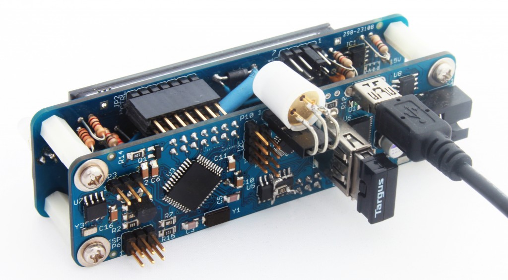 Luminardo with Bluetooth Dongle ‘Targus’ Compile the sketch, upload it to Luminardo, open terminal application, configure select appropriate serial port and baudrate (57600bps in our case) and watch what is being reported. If everything is done correctly you should be able so see something like this:
Circuits At Home 2011
USB Host Shield Quality Control Routine
Modified in Magictale Electronics for testing Luminardo boards
Reading REVISION register... Die revision 03
SPI long test. Transfers 1MB of data. Each dot is 64K................ SPI long test passed
PLL test. 100 chip resets will be performed
Resetting oscillator
Reset number 0 Time to stabilize - 349 cycles
Reset number 1 Time to stabilize - 350 cycles
...
Reset number 99 Time to stabilize - 349 cycles

Checking USB device communication.

Waiting for device...Enabling VBus... enabled
Reset complete. Waiting for the first SOF...
Getting device descriptor
Descriptor Length:      12
Descriptor type:        01
USB version:            0200
Device class:           E0
Device Subclass:        01
Device Protocol:        01
Max.packet size:        40
Vendor  ID:             0A12
Product ID:             0001
Revision ID:            3164
Mfg.string index:       00
Prod.string index:      02
Serial number index:    00
Number of conf.:        01

All tests passed. Press RESET to restart test
If there is ‘All tests passed’ at the end it means that the hardware is functional and USB Host library is configured correctly. The platform is ready for real experiments!
Luminardo motherboard and MVFD 16S8D Panel were specifically designed to fit together. That is why both PCBAs have the same board outline and matching mount holes. Two PCBAs interconnected by a 2 row 14 pin header, named as P8 on motherboard side and as JP2 on VFD panel side. In order to do the assembling we will need 8 x M3x10 screws, 8 x M3 washers and 4 x M3x18 tapped nylon spacers. The process is rather trivial and takes just a few minutes to complete. Assembly parts are shown on the picture below:
 Luminardo Rev1.0 Assembly Parts Assembling process is shown on video below:
Now we would need to use Luminardo source code again (previously we mentioned it here). Install VFD panel library if you haven’t done it so – copy Software\Arduino\Libraries\MVFDPanel_16S8D folder and its content to [ArduinoIDE_Install_Directory]\libraries. Restart Arduino IDE. Open
Software\Arduino\Sketches\Luminardo_MFVD_16S8D_Test\Luminardo_MFVD_16S8D_Test.ino sketch in IDE, make sure that ‘Luminardo 1284P 10MHz’ is still selected and try to compile the sketch. If all previous steps were done correctly, the sketch should compile successfully. Connect Luminardo with previously programmed bootloader to your PC by mini-USB cable. Wait until new virtual COM port appears in Device Manager, select appropriate serial port in Arduino IDE and try to upload the compiled sketch. Be aware of a little trick that helps to program Luminardo: as there is no RESET button in hardware rev1.0 sometimes it becomes difficult for Arduino IDE and the board to initiate handshaking before actual programming takes place. The reason for this is simple: upon boot up control is given to a Luminardo’s bootloader and it waits for incoming request just for a few seconds and if nothing received then bootloader gives control to Luminardo’s main application. On the other hand, Arduino IDE takes more than a few seconds to initiate upload after ‘compile and upload’ button is pressed so by the time when IDE is ready to upload Luminardo’s bootloader has already given up. The best solution for now is to power Luminardo when the Arduino IDE is about to finish compilation and initiate upload, the right moment is chosen experimentally and depends on sketch complexity and PC performance. When sketch upload is in progress two white LED’s on Luminardo motherboard repeatedly flashes to indicate data exchange as shown on video below:
When sketch upload is complete your Luminardo should become alive:
At this stage your Arduino IDE is configured correctly and most of Luminardo hardware is functional. Stay tuned, more tutorials are coming very soon.
Flashing bootloader is probably first priority task following immediately after PCBA soldering and assembling process. A board with bootloader in place significantly simplifies firmware development process, allows not to be dependent on presence of external ISP programmer (such as USBTinyISP). It also allows for seamless integration with well-known and very popular Arduino IDE
As a first step we need to integrate Luminardo core library with Arduino IDE installation. Download latest Luminardo source code, extract the content of zip file. Copy Software\Arduino\Luminardo_Motherboard and its content to [ArduinoIDE_Install_Directory]\hardware as it is shown on the picture below:
 Luminardo Intergation with Arduino IDE Also copy Software\Arduino\Libraries\MVFDPanel_16S8D folder and its content to [ArduinoIDE_Install_Directory]\libraries, we will need it later when it comes to using sketches.
Start Arduino IDE (or restart if it was already running). In a drop-down menu Tools-Board should appear a new item 'Luminardo 1284P 10MHz' as shown on the picture below:
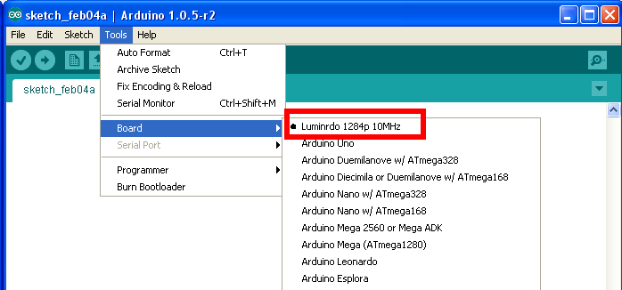 New board ‘Luminardo 1284P 10MHz’ should appear Connect an ISP AVR programmer (for instance, USBTinyISP) to your PC via USB cable and connect programmer’s flat ribbon cable to the 6-pin ISP connector on Luminardo PCBA. Make sure the ISP header is plugged the right way. Also make sure that AVR progammer is providing power supply for the target board (in case of USBTinyISP its PWR jumper is closed. In Arduino IDE select appropriate ISR programmer (in our case it is USBTinyISP), please refer to the picture below:
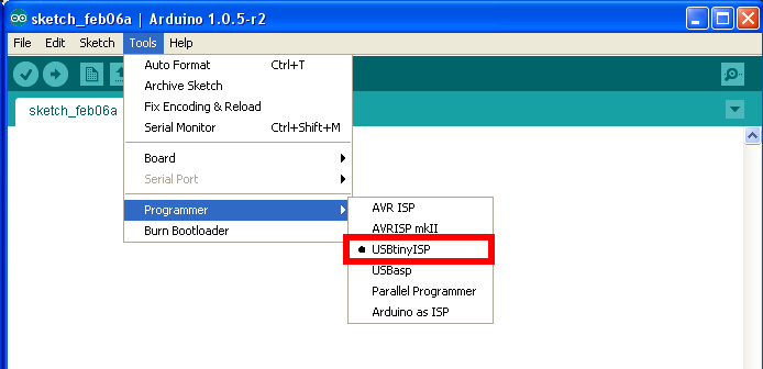 ISP AVR Programmer Selection Initiate bootloader upload process as shown below:
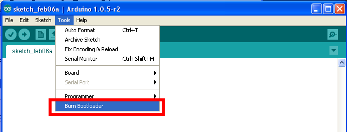 Starting Bootloader Upload Process The process of burning bootloader takes several minutes. No progress indicator of any kind is displayed so be patient. If you are using USBTinyISP then in the end there will be an error message saying that verification failed. This is due to programmer’s limitation according to which it can’t program chips with flash size greater than 64K. However, it is not true – the programmer still does its job, it is only verification that it can’t do for blocks of memory located above 64K boundary. So if you see the following error message you still can consider it as a success:
 Successful Result of Progamming Luminardo Bootloader with USBTinyISP Disconnect ISP progammer from Luminardo PCBA. Connect your PC and Luminardo motherboard via mini-USB cable. One of two white LEDs should briefly flash upon booting up. Your Luminardo is ready to be programmed without external hardware.
|