


Just recently by a pure accident we became involved into very unusual project. Willing to become known to some degree amongst the local Sydney electronics enthusiasts we decided to take part in one of the community projects and help to build something. It didn’t take much time to wait for someone who posted a request asking for assistance to design a LED display panel for engine health status indication. At a first glance it looked like a toy for a remotely controlled plane equipped with a miniature turbine engine. However, it soon turned out to be more serious: the panel was supposed to indicate health status of a full scale twin turbine engine being part of a personal turbine powered aircraft! Display was required to show RPM and temperature for both engines individually and ‘flight time’. All information was requested to be represented by columns of super bright LEDs, the solution would have to be be power efficient, receive data streams from both ECUs (Engine Control Units) via regular RS232 ports, have a capability of firmware update and work in wide range of input voltages (with the efficiency peak somewhere in 15…16V range as it is a typical voltage of the aircraft’s onboard lithium battery).
After doing some preliminary experiments with multiplexed displaying technique we got unsatisfactory results for LED brightness under direct sunlight and decided to go for static indication by using specialised MAX6957 chips which also allow controlling current flowing through each individual LED and therefore allow for programmatically adjustable brightness. On top of that we decided to use USB to serial converter for easier firmware updates/debugging and a photo resistor acting as a light sensor. And here is the result of our effort.
The circuit diagram of the display panel is given below.
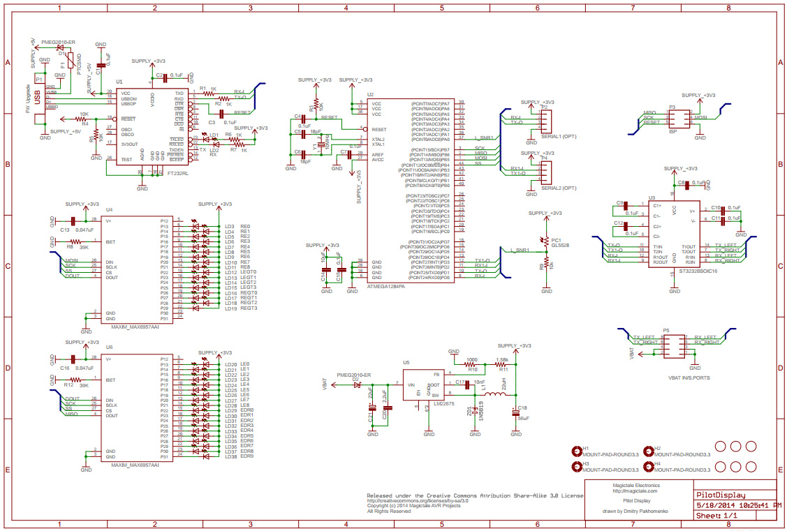
Pilot Display CircuitDiagram Rev.1.0
The PCB layout is done on two layers. Component placement for top and bottom sides are given on the pictures below.
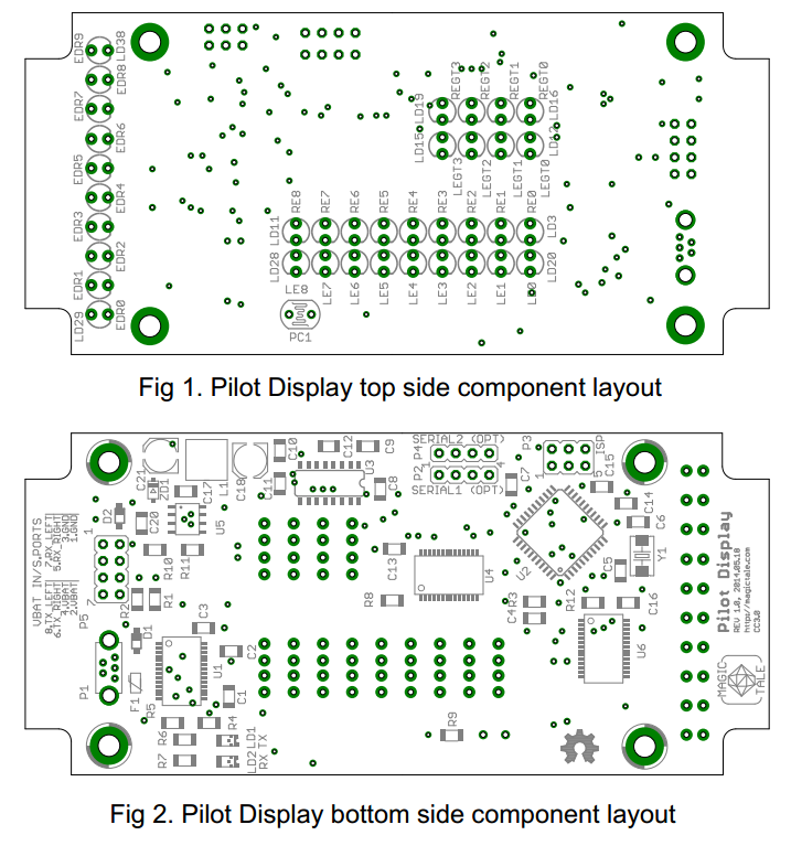
PilotDisplay Component Layout Rev1.0
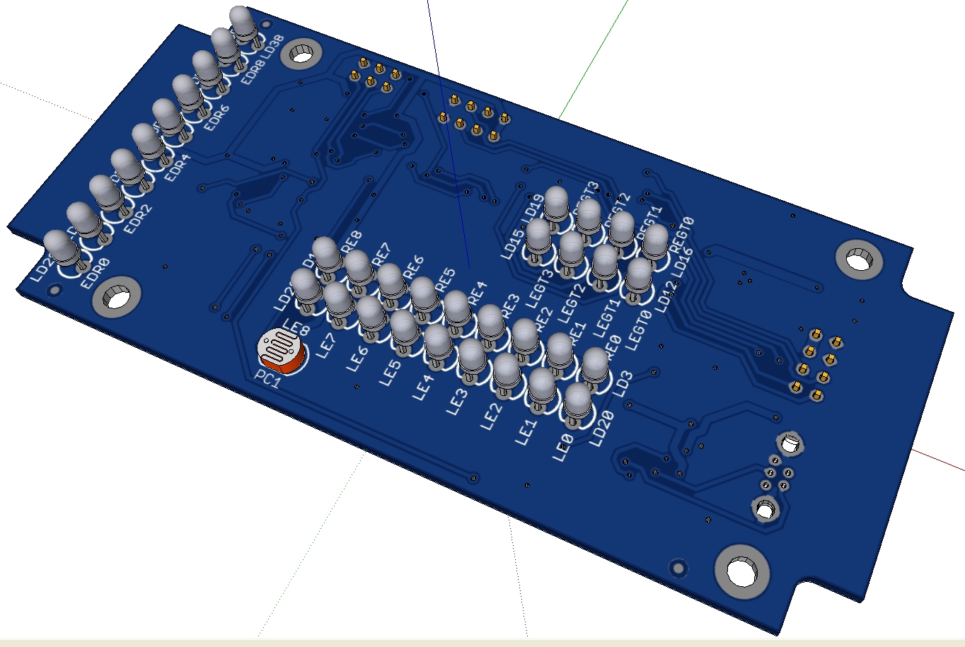
A 3D model of the PCBA and Sketchup snapshots are given below.
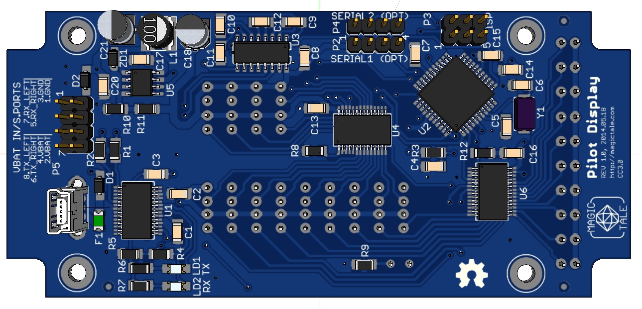
Pilot Display PCBA 3DModel Top View
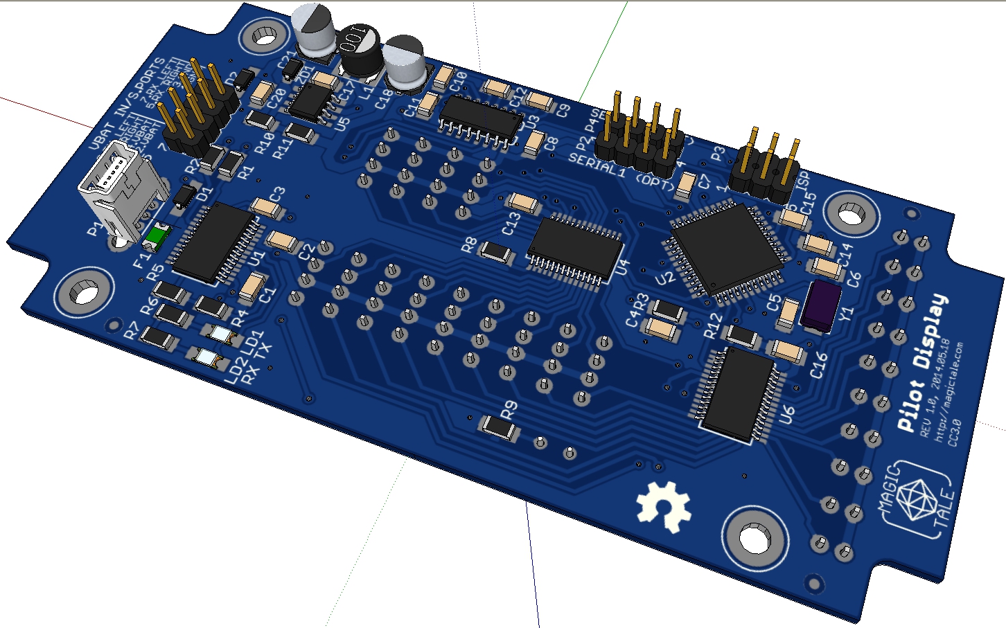
Pilot Display PCBA 3DModel Top ISO View
Pilot Display PCBA 3DModel Bottom ISO View
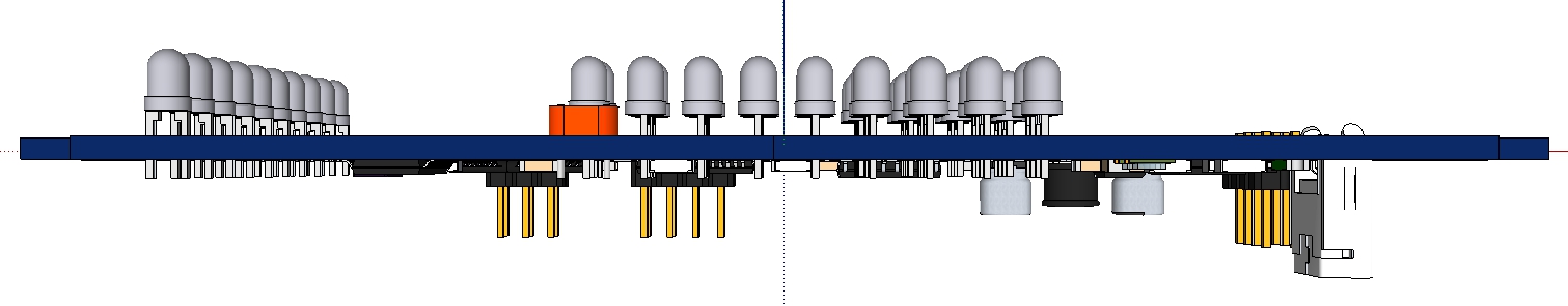
Pilot Display PCBA 3DModel Side View
Downloads:
1. Pilot Display Gerber files Rev1.0
2. Pilot Display Eagle files Rev1.0
3. Pilot Display SketchUp 3D Model Rev1.0
4. Pilot Display Component 3D Models
5. Pilot Display BOM (Bill Of Materials)
Firmware source code is yet to come – stay tuned.


Leave a Reply
You must be logged in to post a comment.