


A foreword
Homemade Linux boards have always been just a pipedream for many due to prohibitive complexity of both hardware and firmware. The situation hasn’t even changed with the arrival of Raspberry Pi and Beaglebone boards which still can’t be replicated in home labs either due to the absence of design files, proprietary components in small quantities or extreme difficulties with hardware manufacturing processes. Apart from the fact that third party hardware doesn’t give warm and fuzzy feeling of a personal achievement there is one substantial problem: a generic third party board can’t naturally fit a custom design. In fact, such board can’t organically fit any design. Just because it was created as a generic multipurpose board. Indeed, has anyone ever seen a goodlooking hardware solution made of an Arduino board and one or more shields? The answer is rather predictable: no. Same applies to the firmware implementation of such solutions, a quick and dirty approach with just one running thread, usage of bit bangs along with busy waits and absolute disregard towards sleep modes. So in pursuit of simplicity another very important characteristic – efficiency is often lost. Off-the-shelf Linux boards help to skip certain steps in development phase but create new problems in exchange. Take a Raspberry Pi, for instance. First version, model A didn’t even have such obvious things as mounting holes. It was designed as a desktop system without provision for powersafe considerations and the board was an inappropriate choice for autonomous robotic platforms. Later models offered more RAM, more performance and more peripherals such as USB ports. Meaning that even more power will be needed which is critical to battery powered systems. Besides, some hardware functionality is just redundant, say, for a mobile platform Ethernet and HDMI ports would be an overkill yet they exist and draw additional current. Raspberry Pi Zero came into play to address those issues but it has its own limitations, it also can’t efficiently cover the whole spectrum of possible applications just because the board was designed generic from the very beginning. Finally, modules and boards always have shorter lifetime than the components they are made of. It means that off-the-shelf boards will become obsolete faster than certain types of CPUs, memory chips etc so designing your own custom board specifically targeting your own user requirements will inevitably give more efficiency and better control in production.
The relevant Internet discussions and rumours have always claimed and still claim that it is extremely difficult if not impossible to build a working Linux board in home environment. To name just a few main challenges, these are: fine pin pitch (or even BGA) packages; necessity to route traces between CPU and memory with impedance and length matching; additional requirements for PCBs such as impedance control, multiple layers and better factory capabilities. The first challenge puts a limit to what can be handsoldered due to either extremely miniature dimensions or physical impossibility to access landing pads with a soldering iron. The impedance and length matching becomes important as SDRAM has high frequency interfaces at which PCB’s dielectric property, trace width and length begin significantly influential on signal propagation causing signal integrity issues in case of improper or sloppy design. The third challenge is higher quality requirements to PCBs and number of layers bigger than two which makes boards more expensive and gets really close to the limit of hobbist’s affordability. However, as it turns out, most if not all challenges can be properly addressed and a reasonable compromise may be found.
Recently we bumped into a very promising opensource minimalistic design of a board capable of running Linux. The project had a name Olinuxino and the simplest board was claimed to be a ‘DIY friendly’ as it didn’t have any BGA packages. We checked the design against the three abovementioned main challenges and to our surprise we found out that all of them were more or less addressed. Indeed, there were no BGA packages whatsoever and the most difficult components to solder were ICs in 66TSOP and 128TQPF packages, 0.7mm and 0.4mm pin pitch. The latter one sounded extreme, the smallest pitch that we had soldered before was 0.5mm. Still, it sounded eminently possible. For the second challenge the project had an elegant solution – it didn’t have impedance and length matching claiming for DDR1 running at 133MHz it wasn’t a must even though it was against SDRAM datasheet. Still, there was a small trick as the DDR IC was placed on the bottom side of the board, strictly under the CPU, minimising the length of high speed traces. Also, each critical trace had the same amount of vias, one, to be more precise. For the third challenge there was also an elegant solution – the board had a layout in just… two layers! And along with the absence of impedance matching requirement it put the board into a definitive DIY category as now it became possible to make it using one of the most popular and cheap service like the one provided by ITeadStudio! Well, in principle as the last statement we were going to prove. Or disprove.
We decided to try to build MX233-OLinuXino-MICRO, the least complicated board of the Olinuxino family and in case of success would get a platform with the following characteristics (pretty impressive if compare with conventional Arduino or mbed platforms):
| IMX233 Olinuxino Micro |
|---|
| – iMX233 ARM926J processor running at 454MHz |
| – 64MB DDR1 running at 133MHz |
| – MicroSD card connector |
| – 1 USB High Speed Host |
| – TV PAL/NTSC output |
| – Three buttons (a hardware Reset and two software configurable buttons) |
| – 2×30 GPIOs for interfacing with external hardware |
Making PCB
A truly DIY design should be eminently reproducible with a truly DIY friendly manufacturer and many would agree that ITead Studio with its PCB prototyping service is a leader here. That is why we found and downloaded ITead_rule.dru from ITead, opened the Olinuxino’s PCB layout and performed a design rule check. At first the outcome turned out to be shocking:
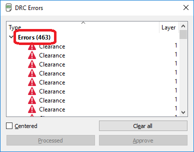
The number of DRC errors, 463 in total was overwhelming. But then we tried to group those errors by types and found out that there were only five types, most of them fell into a category Stop mask collides with either a via or a landing pad. Those kind of errors would be safe to ignore as they didn’t impact electrical characteristics of a board. The second type was a Power trace width error. The analysis revealed that there was a minimum trace width for power traces specified but several traces were breaking the rule. It was due to the fact that some segments physically couldn’t be made any wider as they were routed to SoC’s landing pads as shown on the picture below. No fix for this DRC error was needed:
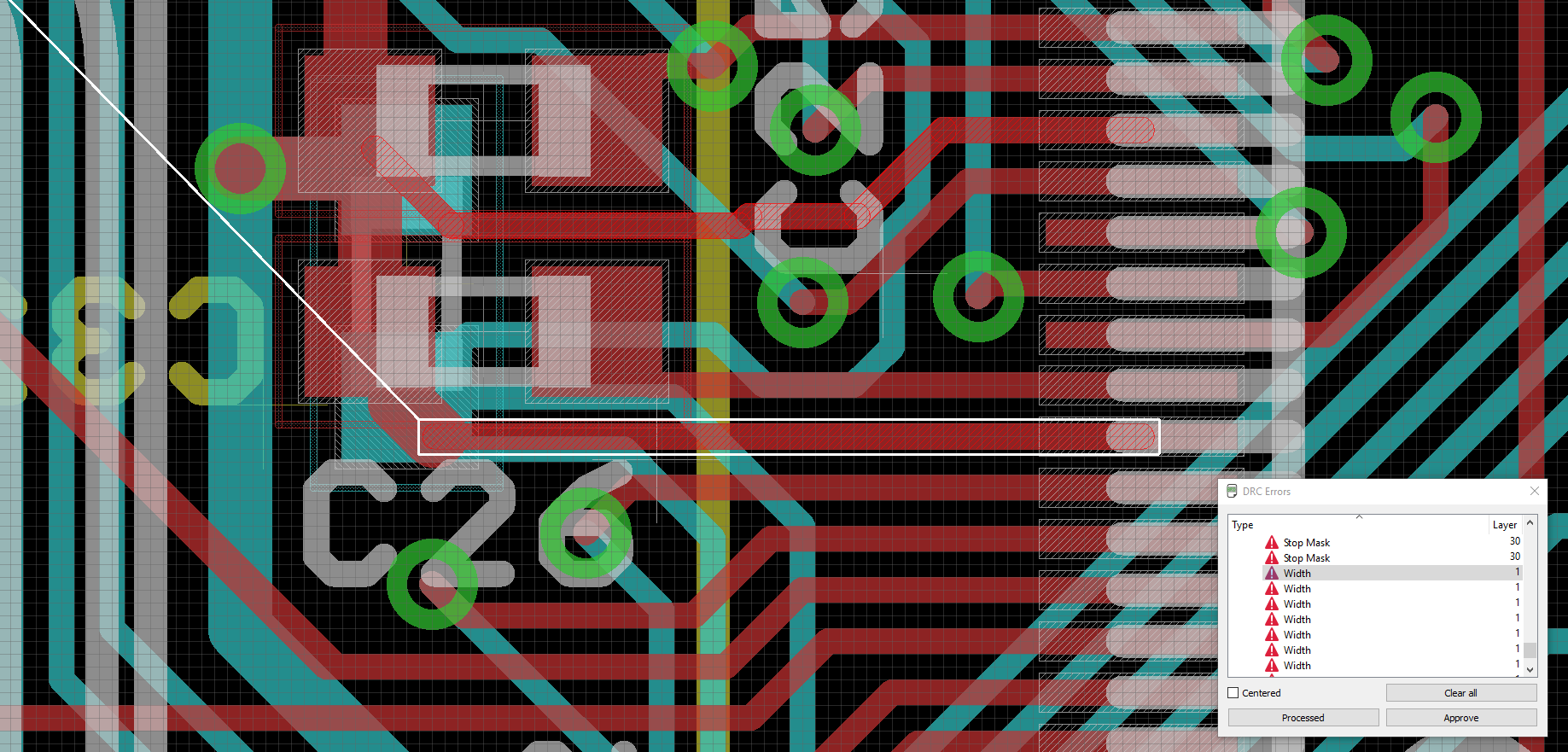
iMX233-OLinuXino Power Trace Width Error
The third type of DRC errors reported about traces overlapping each other as show on the picture below. This was because some jumpers were in ‘closed’ state by default, in other words, they were shorted by a trace causing DRC error. No fix for this errors was needed:
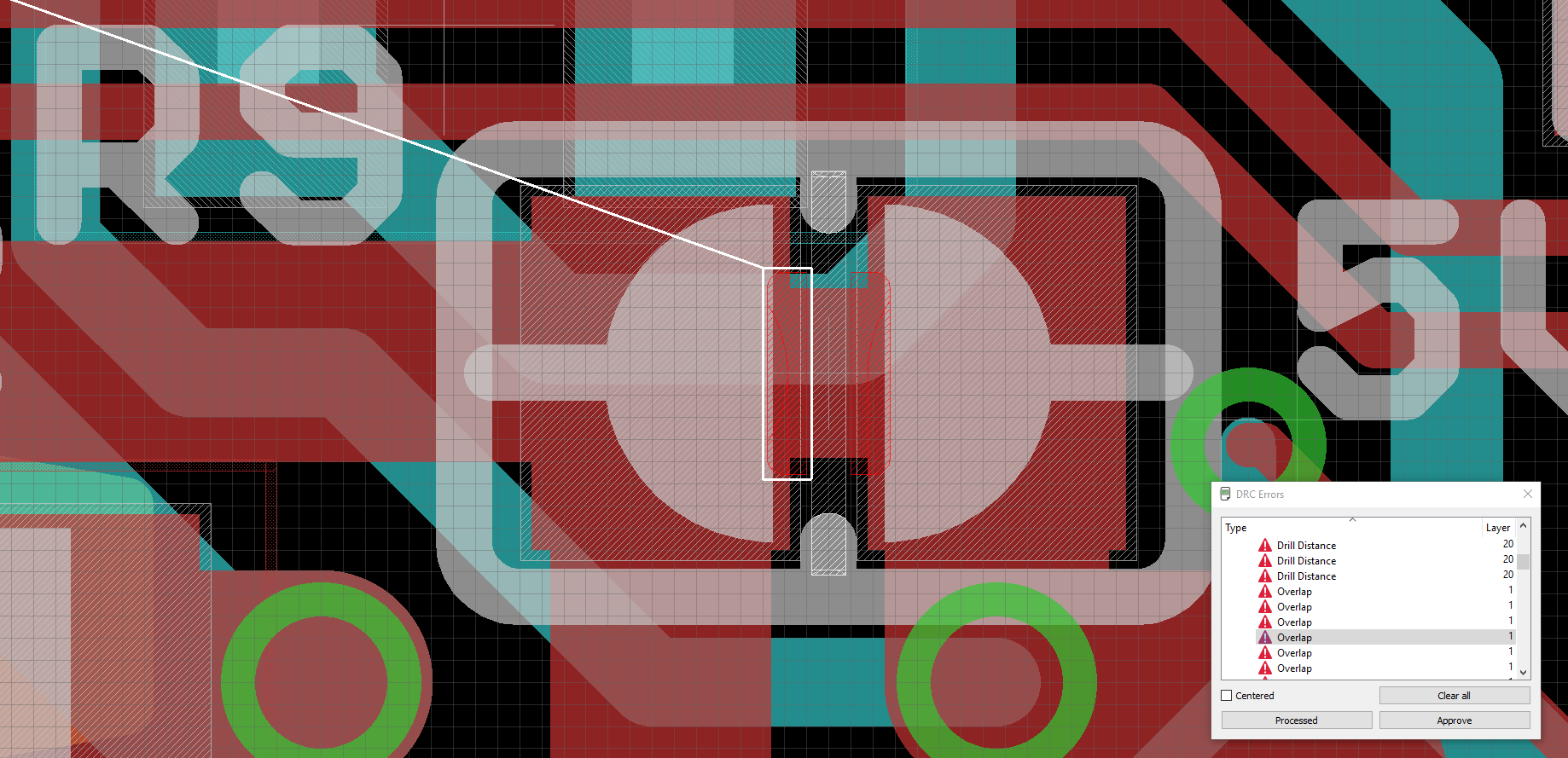
iMX233-OLinuXino Trace Overlap Error
The fourth type of error was about minimum drill distance. Indeed, it makes little sense when looking at the picture below. However, in most cases it will be understood by the PCB manufacturing houses. The thing is that Eagle CAD doesn’t have any means to define slots, not round holes! Yes, that ironic, the product is mature enough, it doesn’t come for free and requires a commercial license, it has became a de-facto standard for thousands of hobbysts and small companies around the globe but still it lacks that very important feature! So by defining multiple overlapping drill holes it becomes possible to specify slot outlines and most factories do interpret this correctly. It is obviously a workaround but it is perfectly legitimate . No fix for this DRC error was needed:
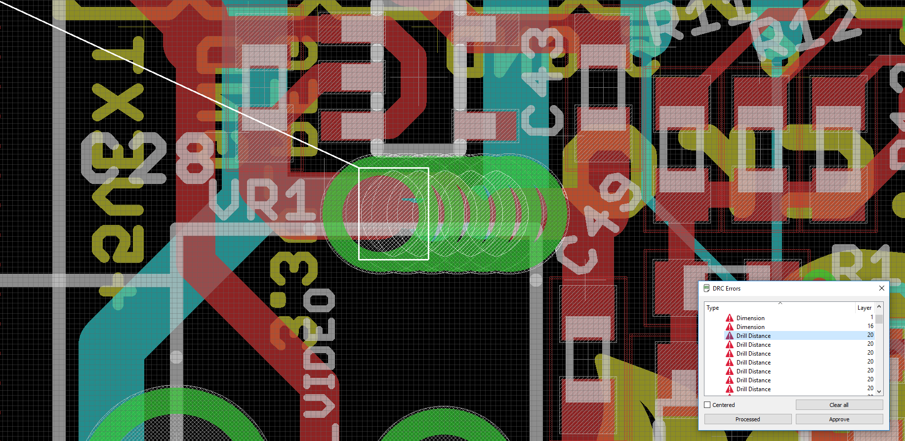
iMX233-OLinuXino Drill Distance Error
The fifth and the last DRC error was about excessively small clearances between several tracks and annular rings. In other words, the tracks were too dense. There were only three problematic areas of that type and they definitely needed a fix. To our surprise, it didn’t take too much effort to add a bit of spacing between them, there was enough of real estate on the PCB. That fact left us a bit puzzled, it was not quite clear why whoever did the initial design made those tracks dense:
iMX233 OLinuXino PCB Layout – Errors to be corrected to comply with iTeadStudio Manufacturing Capabilities
In the end, the design successfully passed the DRC check with warnings which we were happy to accept. The board seemed to match ITead’s capabilities so we submitted our order in no time and making our first big mistake without even realising it. The problem lurked in electronic components and their actual availability. It turned out that not all of them were available on Digikey and we had to hunt on Ebay to get some. Even if there was functional replacement on Digikey it didn’t have either pin-to-pin compatibility or simply had slightly different footprint which would be an easy fix if our PCB design had’t been already in production. As a rule of thumb, it is always a good idea to compile a bill of materials and check component availability before ordering PCB production and this time we didn’t stick to the rule thinking that the proven design shouldn’t suffer from those issues. It was another common mistake though – never make assumptions, always double check.

iMX233-OLinuXino-Micro iTead friendly PCB layout
The original design files didn’t have bill of materials (BOM). Not only that, the circuit diagram didn’t contain enough information to generate BOM. None of the components had a supplier or part number. Many components had values but didn’t have specific requirements such as ESR or ESL values for decoupling capacitors, their tolerances, preferred technology (either ceramic or electrolytic), inductors were also lacking specific parameters which are so important in high frequency circuits. So we had to study the original i.MX233 reference design, search for original manufacturer numbers, find missing parameters and in case of their unavailability look for appropriate replacement. Some components gave us really hard times as we couldn’t even find any useful information about parts like the mircoSD card. It had many names and was designed by a noname Chinese company making it very hard to identify and obtain. Eventually the BOM had been compiled but several parts had to be purchased from Ebay, these were the microSD memory card (refnum SD/MMC), 512MB DDR (refnum U2, later we discovered that there was a direct substitution available on Digikey), and a USB power switch (refnum U3). Also, we didn’t find a crystal (refnum Q1) with the required stability (it was defined as 20ppm yet we managed to find only 30ppm, it was 24MHz instead of 24.000MHz and its capacitance wasn’t specified anywhere so we used 20pF). Knowing that the i.MX233 was very sensitive to the crystal parameters we were not so sure if our part would work and were emotionally prepared for instabilities). For each part a 3D model has been created and we had an opportunity to check the fitment of each component even before the actual boards were manufactured. The 3D model of the whole assembly is available at 3D Warehouse so it becomes really easy to design extension boards or enclosures.
The rendered top and bottom views of the PCB’s 3D model are given below:
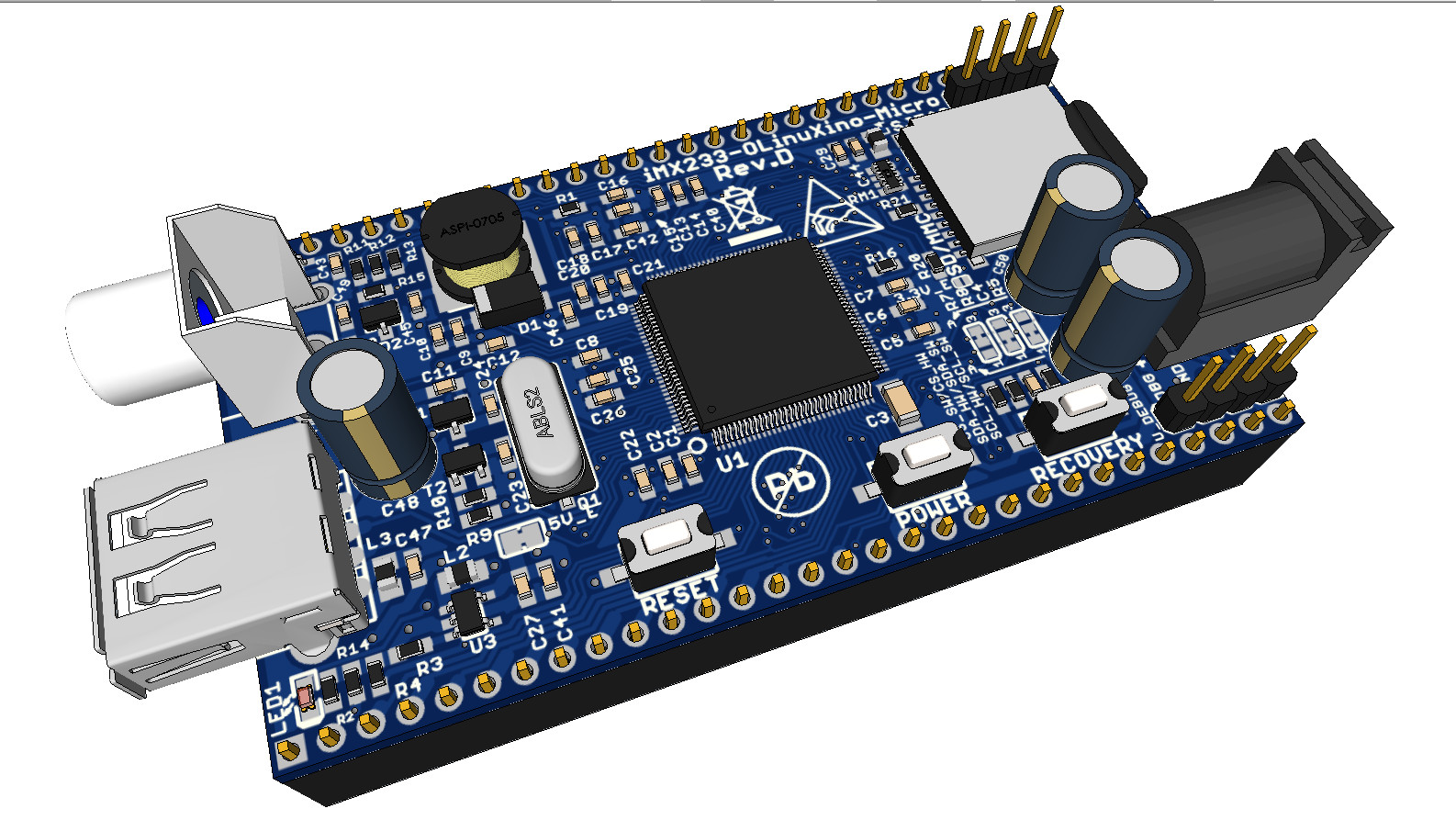
iMX233-OLinuXino-Micro iTead Friendly PCBA, 3D Top View

iMX233-OLinuXino-Micro iTead Friendly PCBA, 3D Bottom View
Soldering components
The manufactured boards arrived from ITeadStudio. We picked one of them and gave it a careful look using an inexpensive USB microscope. It became obvious that our design was really close to the factory’s capabilities: many via drills were slightly off-centre of their annular rings, straight lines of the silkscreen and the copper traces were visibly wobbly. It wasn’t perfect but it didn’t look bad either. With all components being already in our stock it was the time to start actual soldering. We didn’t have in our possession any reflow oven nor pick-and-place machine. Instead, a soldering station for amateurs, TS1390 from Duratech was used. The most difficult two components to solder were obviously U1 and U2, the latter one was a bit easier. We decided to start off with these two as there was no guarantee that it would be possible at all and at first practiced with U2. As an experiment, we decided to try using soldering paste and by doing this made a big mistake. Without use of a proper paste dispenser the amount of soldering paste on each pad and around it becomes uncontrollable causing excess of paste remain unsoldered and trapped between pins and IC’s package. That excessive paste can cause short circuits and it is very difficult to remove.
ITead friendly OLinuXino-Micro blank board
The biggest challenge during soldering U1 was to accurately position it in such a way that all four rows of pins would rest exactly on their pads. For us it actually took more time than the actual soldering. We temporary soldered two pins diagonally then triple checked and confirmed the operation with a microscope. Finally we gave ourselves a go to solder the remaining pins. Inevitably, many of the adjacent pins became shorted during the process, this was later rectified with the help of a de-solder braid. Finally everything was carefully checked under microscope again. However, at that time we overlooked the remnants of the soldering paste which is still visible behind the pins on the picture below:
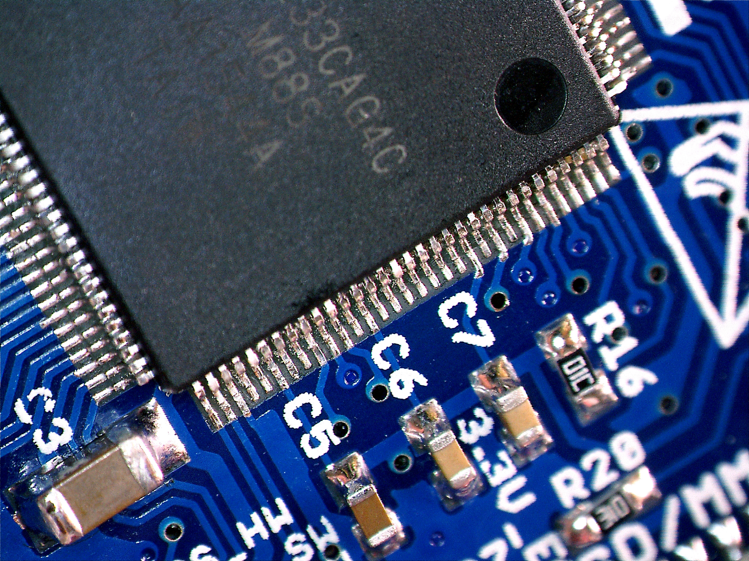
Hand soldered 128-LQFP (14×14)
After soldering the two most difficult components the rest was simple. No doubts, there was still need for a steady hand as most of the capacitors and resistors were in 0306 packages which require delicate handling but there was nothing extremely hard here. The fully assembled board was cleaned to remove flux and was inspected through a microscope again. The board looked almost like its 3D model as it is seen on the pictures below:
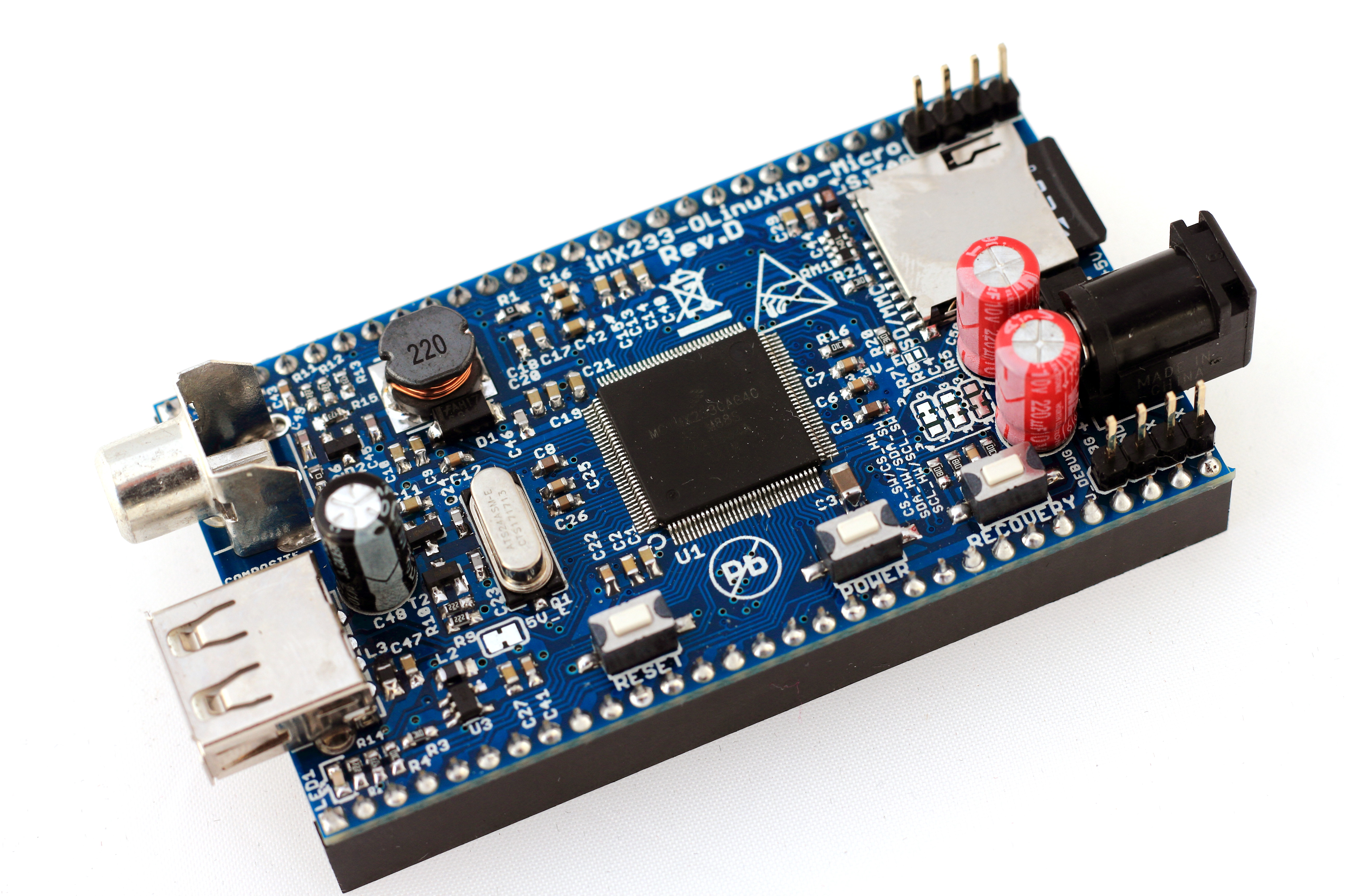
ITead friendly OLinuXino-Micro assembled top view
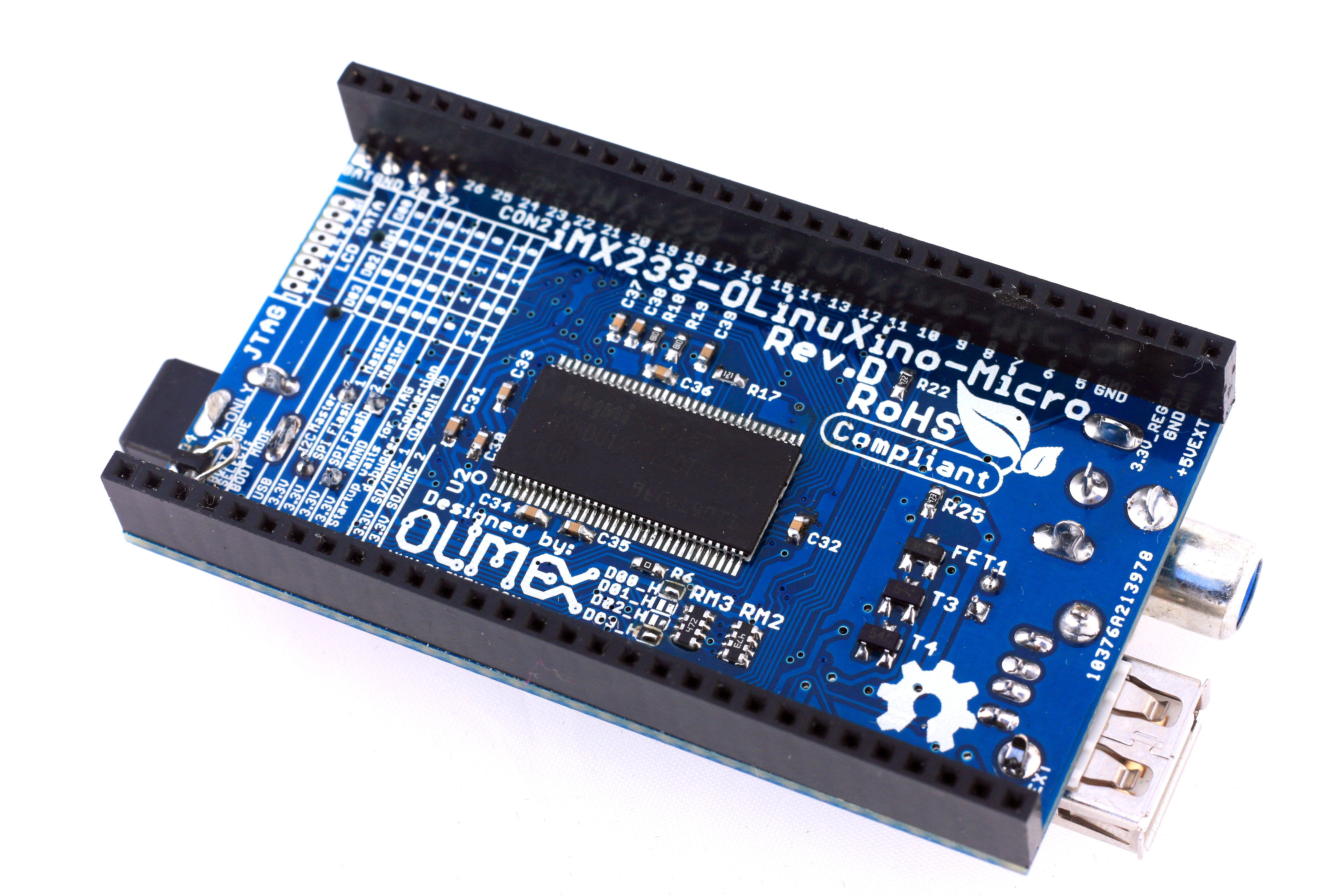
ITead friendly OLinuXino-Micro assembled bottom view
Applying power
The next step was to apply power for the first time and evaluate current consumption. To do this safe way there was a need for a regulated power supply with overcurrent protection. We set up our bench power supply to 5V and limited current to just 500mA then applied power to the board through the power jack PWR. To our surprise, the was no smoke or anything bad. The bench power supply indicated 5mA current consumption and it seemed to be too low to be truth. Shortly after we found some information in the Internet stating that in non-initialised mode the current consumption is expected to be around 6mA due to the fact that most SoC subsystems are still switched off and DRAM is not yet configured so the consumption is minimum. And if so, our board passed the first test.
Building a kernel
The process is described in detail at https://github.com/koliqi/imx23-olinuxino. However, at the moment of writing this article the original information was at least 5 years old and while trying to follow the guide we encountered many differences. This is why we decided to post a full updated instruction here. We were using the following Linux distributive:
Description: Ubuntu 16.04.3 LTS
Release: 16.04
Codename: xenial
All subsequent interactions are made through a terminal. Make sure that a cross compiler and git are installed:
$: sudo apt-get install git
Get the Freescale bootlets, patches for them and elftousb2 utility:
Switch into directory kernel and download kernel sources:
$: wget http://www.kernel.org/pub/linux/kernel/v3.0/linux-3.7.1.tar.bz2
$: tar xvjf linux-3.7.1.tar.bz2
$: mv linux-3.7.1 linux-stable
Switch into directory linux-stable and apply patches:
$: patch -p1 < ../0001-MXS-imx23-olinuxino-Add-i2c-support.patch
$: patch -p1 < ../0001-ARM-imx23-olinuxino-Add-spi-support.patch
$: patch -p1 < ../0001-rtl8192cu.patch
Configure kernel:
$: make ARCH=arm CROSS_COMPILE=arm-linux-gnueabi- menuconfig
Select Boot options —> and select following options:
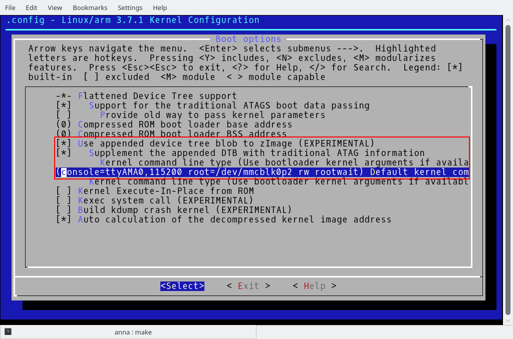
Linux Kernel 3.7.1: configuring Boot Options
To enable driver rtl8188cu first enable Multi-purpose USB Networking Framework:
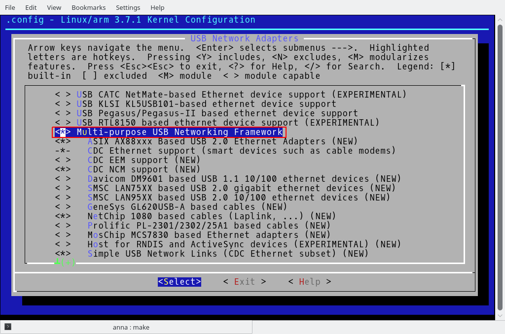
Linux Kernel 3.7.1: enabling multi-purpose USB networking framework
Then activate IEEE 802.11 networking stack:
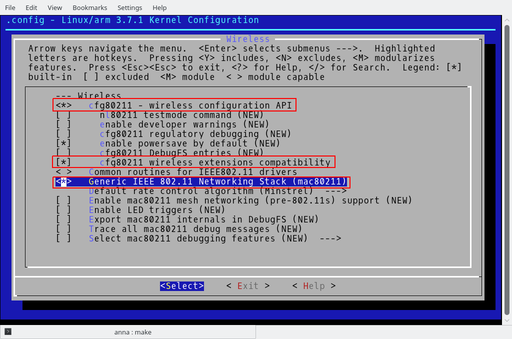
Linux Kernel 3.7.1: activating IEEE 802.11 networking stack
And activate Realtek 8192C USB WiFi and IEEE 802.11 for Host AP:
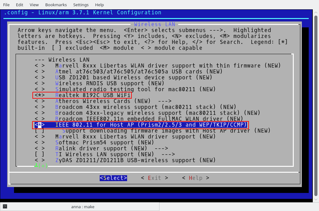
Linux Kernel 3.7.1: activating Realtek 8192C USB WiFi and IEEE 802.11 for host AP
Power LED need to have default ON trigger activated on kernel:
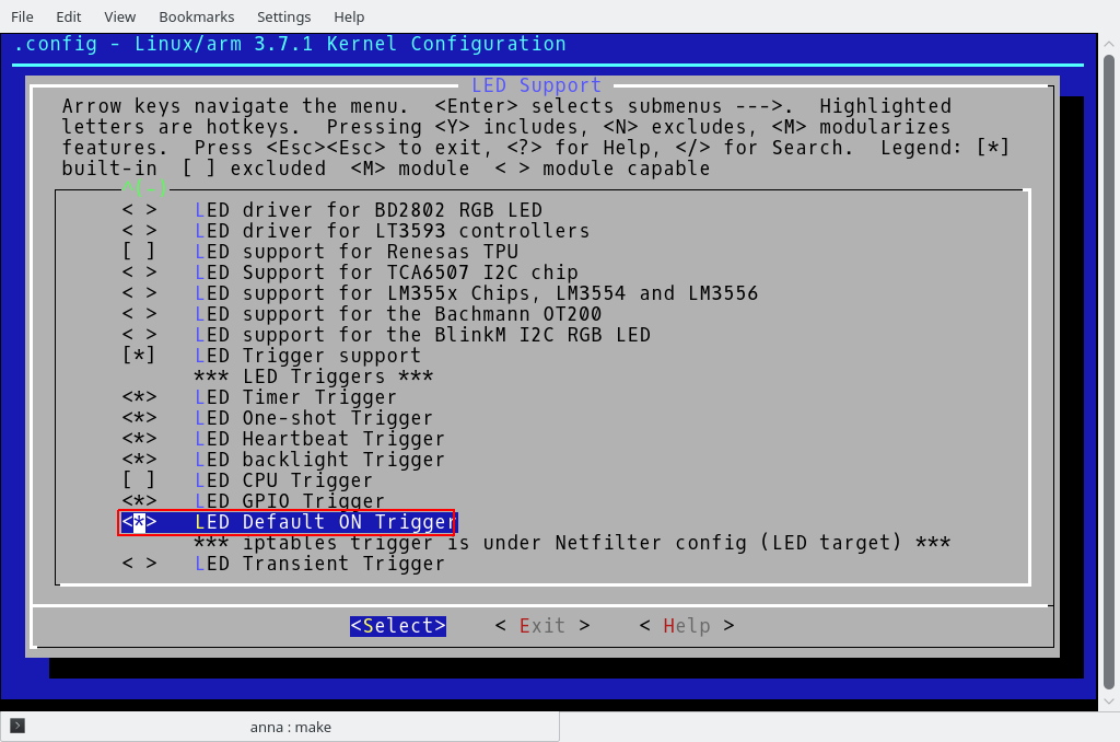
Linux Kernel 3.7.1: enabling LED default on trigger
Activate other drivers as needed. Save and exit from menuconfig application.
Compile kernel:
*NOTE that in our environment the kernel compilation failed due to the following reasons:
-
An exception
Can't use 'defined(@array)' (Maybe you should just omit the defined()?) at kernel/timeconst.pl line 373'generated by Perl compiler. It turned out that defined has been deprecated in newer versions of Perl (newer versions of Perl) and we had to remove it from the code; - By default in our environment a version 5.0 of the arm-linux-gnueabi-gcc was installed which had some incompatibilities introduced since version 4.7 and only that earlier version was capable of compiling the old code. There is a method of having multiple revisions of the compiler installed on the system, the explanation on how to do it could be found here. In our case, we ended up using version 4.7.4.
When compilation successfully finishes, it is ready at arch/arm/boot/zImage
Create device tree blob .dtb file:
Join zImage and imx23-olinuxino.dtb into a new file zImage_dtb:
If you want to repeat this procedure, start with clean-up:
$: make ARCH=arm CROSS_COMPILE=arm-linux-gnueabi- clean
The iMX23 SoC contains a built-in ROM firmware capable of loading and executing binary images in special format from different locations including MMC/SD card and NAND flash. Binary image is called a boot stream (.bs). Boot stream consists of a series of smaller bootable images (bootlets) such clock bootlet, power bootlet etc. Linking bootlets with kernel and converting from elf format to raw boot stream is done with utility elftobs. In this package, utility elftobs2 is located in directory elftosb-0.3. Switch into directory elftosb-0.3 and make symbolic link into compilers default PATH:
Check with locate:
elftosb2 should be located at /usr/sbin/elftosb2. Next, switch into directory boot and untar archive imx-bootlets-src-10.05.02.tar.gz:
Then switch into directory imx-bootlets-src-10.05.02 and apply patches:
This patched package require zImage in this directory. We have created zImage_dtb instead, so make symbolic link as:
Make boot stream file:
$: make CROSS_COMPILE=arm-linux-gnueabi-
Final response would be:
The bootloader is ready and it is written as sd_mmc_bootstream.raw
Making bootable SD card
Insert your SD card into a card reader of your Linux machine and list partition tables for all disks:
Identify your SD disk. In this example SD disk is recognized as /dev/sdb. Unmount all mounted partitions, i.e. sudo umount /dev/sdb2. Run fdisk:
- Press 'p' to show the partitions on the card
- Press 'd' to delete a partition. Repeat to remove all partitions
- Press 'n' to create a new partition
- press 'p' to select the primary partition
- press '1' for creating partition 1 on the card
- press Enter to start from first block
- Type '+16MB' to create the 16MB partitions
- Press 't' to change the newly created partition type
- Enter '53' for the new partition type
- Press 'n' to create a second partition
- Press Enter to accept all default setting
- Press 'w' to write the partitions to the card and exit the fdisk
In this example SD disk is recognized as /dev/sdb. Format the second partition on the SD card:
Make mount point directory /mnt/mmc
Mount the partition /dev/sdb2 on mount point directory /mnt/mmc:
Download and extract the root filesystem (as root, not via sudo):
bsdtar -xpf ArchLinuxARM-armv5-latest.tar.gz -C mnt
umount mnt
sync
Install the bootloader which we already created to the first partition (in our system sd device is /dev/sdb1):
$: sudo sync
The card is ready.
Boot mode and serial output
The iMX233 SoC has multiple boot sources such as USB, I2C, SPI, JTAG, SD/MMC card and so on. In order to make it boot from our SD card we had to specifically instruct it to do so. There are two ways of doing this, either by setting up jumpers or programming OTP bits. Each approach has its own pros and cons. Jumpers are easy to use and they allow multiple reconfigurations, however, they reduce the amount of available GPIO lines. The OPT bits can be programmed only once and in case of misconfiguration the board in essence becomes a piece of junk. There is also a need to a USB A-A cable and special piece of software called ‘BitBurner’ which runs on… Windows only! The software is available here. Initially we chose to use the jumpers but it turned out that under certain circumstances they don’t work. There were many people complaining in the Internet about the same issue without any working solution so we decided to switch to OTP. We downloaded the BitBurner, extracted the executable, run it, connected the board to our PC running Windows and applied power to the board. Then with the help of BitBurner we blew SD MBR Boot[3] to ‘1’ and SD_POWER_GATE_GPIO[21:20] to ’10-PWM3′ as it was advised in OlinuXino Micro User’s Manual.
In order to see console output there is a need for an external USB-To-Serial adaptor. There are many different types of them nowdays and it doesn’t really matter which one to use. There are two things to keep in mind though: an adapter must have 3.3V outputs as Olinuxino’s GPOIs are not 5V tolerant. Also, the second thing to consider for the adapter is its ability to work under Linux as there are a lot of activities which need to be done in that operating system and it simply becomes impractical to switch constantly Windows and Linux. As for us, we didn’t have one and we rushed to Jaycar to buy this Arduino compatible USB to serial adaptor module. It had a 3.3/5V switch and worked under Linux without issues, however, looked like that it was overpriced. We made sure to switch it to 3.3V mode, connected its GND, TXD and RXD with appropriate pins of OlunuXino’s U-DEBUG connector and… at that stage we were ready for our first Linux boot.
Booting up Linux
Everything seemed to be ready for the first experiment with the Linux bootup. MicroSD card was prepared and inserted into OlinuXino’s socket, OTP bits were programmed, USB-to-serial adapter was connected to the board and hooked up to a PC, terminal application was configured to read data at 115200bps, we set up our bench power supply to 5V and limited current by 500mA. Then double checked everything and at last dared to apply the power. And this was what we saw in the console:
HTLLLLLLLLLLLLLLLLLLLLLLLLLLLLLLLLLLLLLLLLLLLLLLLLLLLLLLLLLLLLLLLLLLLLLLFC
PowerPrep start initialize power...
Battery Voltage = 0.00V
No battery or bad battery detected!!!.Disabling battery voltage measurements.
LLCJan 4 201321:57:25
EMI_CTRL 0x1C084040
FRAC 0x92926192
init_ddr_mt46v32m16_133Mhz
power 0x00820710
Frac 0x92926192
start change cpu freq
hbus 0x00000003
cpu 0x00010001
LLLLLLLFCLJ
Undefined Instruction
Let’s analyse what happened. The booting process obviously failed shortly after it started. The failure was ‘Undefined instruction’ which could be caused by an image incorrectly built or due to some hardware issue. But from the log it became obvious that a CPU was properly clocked and able to fetch and execute instructions. It also was able to boot from the SD card which meant that OTP bits were programmed correctly. It also detected DDR and tried to ramp up its clocking frequency before failing to continue.
Our first impression was that we build the kernel using incorrect target CPU. But then we prepared SD card with already precompiled U-boot described here and got exactly the same result. The suspicion fell on the hardware. We needed to test our RAM somehow. Looking at the source code of the bootlets we found that a memory test was simply disabled in imx-bootlets-src-10.05.02\boot_prep\init-mx23.c :
#if 0
	/*Test Memory;*/
	printf("start test memory accress");
	for (i = 0; i < 100; i++)
		*pTest++ = i;

	pTest = (volatile int *)0x40000000;

	for (i = 0; i < 100; i++) {
		if (*pTest != (i)) {
			printf("0x%x error value 0x%x\r\n", i, *pTest);
		}
		pTest++;
	}
#endif
So the next step was to enable the memory test, recompile the kernel, re-build the SD-card and try to boot from it again. The results were blankly pointing at issues with the memory:
...
start test memory accress0x00000000 error value 0x00000009
0x00000001 error value 0x00000009
0x00000002 error value 0x00000009
0x00000003 error value 0x00000009
0x00000004 error value 0x00000009
0x00000005 error value 0x00000009
0x00000006 error value 0x00000009
0x00000007 error value 0x00000009
0x00000008 error value 0x00000009
0x0000000A error value 0x00000009
0x0000000B error value 0x00000009
0x0000000C error value 0x0000000D
0x0000000E error value 0x0000000D
0x0000000F error value 0x0000000D
0x00000010 error value 0x00000019
0x00000011 error value 0x00000019
0x00000012 error value 0x00000019
0x00000013 error value 0x00000019
...
It looked really bad. It simply suggested that three if not four bits on data didn’t work. We were prepared for some bad soldering issues but four bits sounded devastating. The result was always the same, no matter how many times we run the test so it didn’t look like faulty memory, it rather looked like soldering issues (either broken or soldered together traces). We studied to PCB layout and couldn’t really figure out what should go wrong in order to get such an effect. It simply didn’t look like any adjacent traces accidentally joined. Then we changed the test. We only send to the console ten consecutive values ten times, after every simple writing operation to the memory. And it turned out that a write to a single address caused values at more than one address to change. From that point it also suggested that there were issues with address bus too.
Then we simplified the test even more. We wrote only one value 0x12345678 at address 0x0 and then read values from 0x0...0x9. The result was as follows:
0x12345678
0x12345678
0xE1A03081
0xE1A03081
0x12345678
0x12345678
0xE1A03081
0xE1A03081
0x12345678
0x12345678
It looked like non-working address lines A0, A2, A3 at least. It was simply too much. We found a good binocular microscope and started peering into the board. To our shock, we saw multiple islands of soldering paste behind the pins. Those paddles of unmelted balls of solder were shorting the pins and the worst part was that washing the board couldn’t help with removal of the paste. But finally we found a solution – a paintbrush with small but stiff bristles which could penetrate behind the pins. With help of a paintbrush we could improve the situation to such an extent when the soldering balls couldn’t create shorts anymore but still couldn’t completely get rid of them. And finally, the microscope revealed one bad soldering case of a DDR pin on the address bus. After fixing the issues the memory test passed.
Finally this is what we got on the serial console:
Downloads:
1.iMX233-OLinuXino-Micro (Rev.D) iTead friendly Gerber files
2.iMX233-OLinuXino-Micro (Rev.D) iTead friendly Eagle files
3.iMX233-OLinuXino-Micro (Rev.D) iTead friendly PCBA 3D model
4.iMX233-OLinuXino-Micro (Rev.D) iTead friendly component 3D models
5.iMX233-OLinuXino-Micro (Rev.D.01) iTead friendly Bill of materials
References:
1.Henrik’s blog: making embedded Linux computer
2.Official Olinuxino Micro manufacturer’s page
3.Single board PC based on iMX233
4.Soldering a fine-pitch QFP
5.Kernel 3.7.1 for the OlinuXino
6.OlinuXino on archlinuxarm.org
7.Getting Started with the Olimex A13-OLinuXino-MICRO
8.Разработка одноплатного компьютера с нуля. Пособие для начинающих
9.BitBurner v1.0.4.6
10.OlinuXino Micro User’s manual
11.Freescale I.MX233 Embedded Linux System
12.Yocto Project
13.Rascal Micro Project
The conclusion
It has been proven that it is eminently possible to built a two layer board capable of running Linux in home environment without expensive equipment and for a price affordable to an ordinary hobbist.


Leave a Reply
You must be logged in to post a comment.