


Today we are publishing photos of fully assembled and tested MVFD 16S8D Panel, Rev 2.0. The board on the pictures is fully populated with components which means that apart from displaying alphanumeric information it can measure ambient light intensity, emit simple ‘beep’, receive signals from an IR remote control and shine with an RGB LED. As it is seen, the majority of components are located on the back side of the board so the top side looks really simplistic. It is worth mentioning that due to the use of through hole components and the fact that components are loaded on both sides the VFD glass should be soldered last during assembling process otherwise it would block access to some through hole pins.
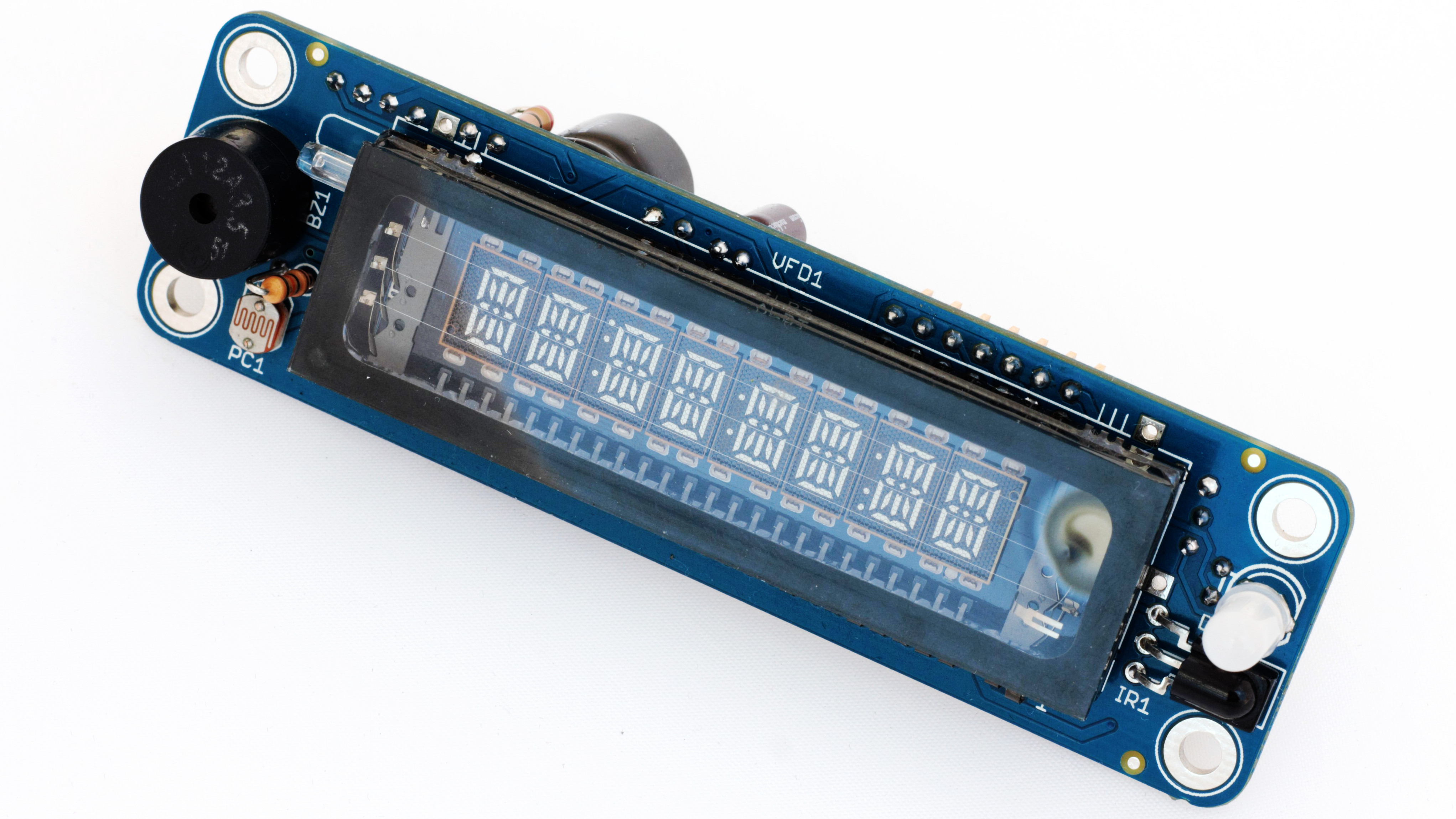
MVFD 16S8D Panel PCBA Front Rev. 2.0
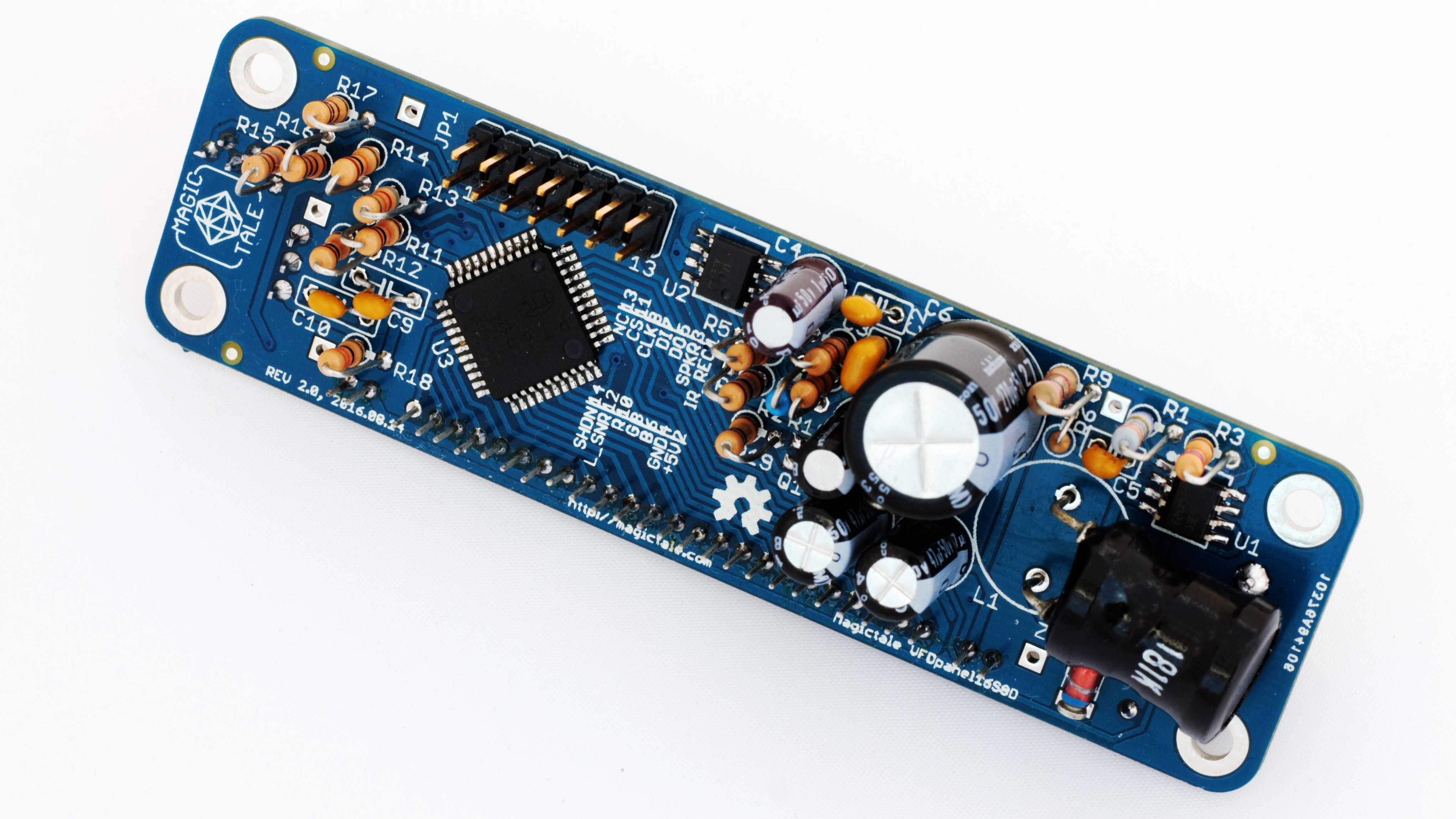
MVFD 16S8D Panel PCBA Back Rev. 2.0
The VFD Panel perfectly mates with either Luminardo board or MVFD Serial Backpack. However, it is also possible to drive it using basic Arduino such as Arduino Duemilanove which has not so many GPIO pin and equipped with only 32K of program memory. If needed, the number of wires can be reduced by eliminating features which are not used – for example, RGB LED, ambient light sensor, IR receiver or speaker.
| MVFD Panel and Arduino Duemilanove pin mapping | ||
| Designation | VFD Panel JP1 pin | Arduino pin num/pin type |
|---|---|---|
| IR RECEIVER | 1 | 2/digital |
| +5VDC | 2 | 5V/PWR |
| SPEAKER | 3 | 9/digital |
| GND | 4 | GND/PWR |
| DO | 5 | 11/digital |
| BLUE LED | 6 | 3/digital |
| DI | 7 | 10/digital |
| GREEN LED | 8 | 6/digital |
| CLOCK | 9 | 8/digital |
| RED LED | 10 | 5/digital |
| CHIP SELECT | 11 | 7/digital |
| LIGHT SENSOR | 12 | 0/analog |
| SHUTDOWN | 14 | 4/digital |
Driving VFD Panel is extremely simple as all heavy lifting is done by MVFD library. All that a developer needs to do is to physically wire the panel to Arduino board (of course), define VFD pins (an example is provided below) and initialise display. From that point controlling the panel becomes as easy as writing to a serial port.
#ifndef Board_h
#define Board_h

#define VFD_SPRK_PIN    	9
#define VFD_CS_PIN   		7
#define VFD_SCLK_PIN 		8
#define VFD_DATAI_PIN 		10
#define VFD_DATAO_PIN 		11
#define VFD_SHDN_PIN    	4
#define VFD_R_PIN       	5
#define VFD_G_PIN       	6
#define VFD_B_PIN       	3
#define VFD_LIGHT_SNR_PIN	0
#define VFD_IR_REC_PIN		2

#endif
The library contains a fair amount of embedded tests and demo effects so the first sketch showing the panel’s capabilities would be also simple (see below). The sketch makes use of a buzzer (you should hear a short ‘beep’ upon Arduino’s start), of an ambient light sensor (there is a demonstration of ‘day’ and ‘night’ modes), of the RGB LED (it pulsates during normal operation and flashes upon bootup and when an IR command is received and encoding standard is recognised). During the test the display demonstrates alphanumeric information, brightness control, flashing (blinking) effect and effect of scrolling line.
#include <util/delay.h>
#include <MVFDPanel_16S8D.h>
#include <IRremote.h>
#include <IRremoteInt.h>

#include "Board.h"

#define MAIN_LOOP_DELAY 150

uint8_t sysState;
uint8_t last_sysState;
uint8_t waitCntr;
uint8_t redValue;
uint8_t greenValue;
uint8_t blueValue;
IRrecv irrecv(VFD_IR_REC_PIN);
decode_results results;

enum enum_SysState
{
sysSelfTest,
sysDispScroll,
sysDispWait,
sysDispParams,
};

MVFD_16S8D vfd(VFD_CS_PIN, VFD_SCLK_PIN, VFD_DATAI_PIN, VFD_SHDN_PIN);    //VFD display

const char SCROLLING_DEMO[] PROGMEM = "        SCROLLING DEMO";

void setup()
{
Serial.begin(57600);

vfd.initLED(VFD_R_PIN, VFD_G_PIN, VFD_B_PIN);
vfd.initLightSensor(VFD_LIGHT_SNR_PIN);

irrecv.enableIRIn();

vfd.standby(false);

redValue = 0;
greenValue = 0;
blueValue = 0;

vfd.setLED(redValue, greenValue, blueValue);

pinMode(VFD_DATAO_PIN, INPUT);
vfd.reset();

tone(VFD_SPRK_PIN, 2048, 500);

vfd.setB_LED(255);
_delay_ms(100);
vfd.setB_LED(0);
_delay_ms(100);

vfd.setB_LED(255);
_delay_ms(100);
vfd.setB_LED(0);
_delay_ms(500);

vfd.setR_LED(255);
_delay_ms(100);
vfd.setR_LED(0);
_delay_ms(100);

vfd.setG_LED(255);
_delay_ms(100);
vfd.setG_LED(0);

sysState = sysSelfTest;
}

void vfd_print_f(char* str, uint8_t idx)
{
char c;
if(!str) return;
while (c = str[0])
{
vfd.write_f_char(c, idx, false);
idx += VFD_BYTES_PER_DIGIT;
str++;
}
}

void updateLEDs()
{
blueValue++;
if (blueValue > 60)
{
blueValue = 0;
}
if (blueValue < 30)
{
vfd.setLED(blueValue/1.17, blueValue/8.6, blueValue);
}else
{
uint8_t newVal = (30 - (blueValue - 30));
vfd.setLED(newVal/1.17, newVal/8.6, newVal);
}
}

void loop()
{
uint16_t lightSen = 300;
uint8_t lightConditions = true;
uint8_t loopCntr = MAIN_LOOP_DELAY / 10;
char num_buf[8];

while (1)
{
loopCntr++;
updateLEDs();

if (loopCntr >= 10)
{
loopCntr = 0;

switch (sysState)
{
case sysSelfTest:
{
if (vfd.testStep() == vfd.COMPLETED)
{
sysState = sysDispScroll;
redValue = 0;
greenValue = 1;
vfd.initScroll_p(SCROLLING_DEMO);
}
break;
}

case sysDispWait:
{
waitCntr--;
if (waitCntr == 0)
sysState = last_sysState;
break;
}

case sysDispScroll:
{
if (!vfd.scrollStep())
{
sysState = sysDispParams;
}

break;
}

case sysDispParams:
{
vfd.setCur(0);

if (lightConditions)
vfd.print_f_p((const char*)F("DAY "));
else
vfd.print_f_p((const char*)F("NGHT "));

lightSen = vfd.getLightSensorVal();
itoa(lightSen, num_buf, 10);

vfd_print_f((char*)&num_buf, 5 * VFD_BYTES_PER_DIGIT);

vfd.flipFrame();

break;
}
default:
;
}

//Handling RC commands
decode_results rc_code;
if (irrecv.decode(&rc_code))
{
vfd.setLED(redValue, greenValue, 255);

vfd.setCur(0);
if (rc_code.decode_type == NEC)
{
vfd.print(F("NEC  "));
}else if  (rc_code.decode_type == SONY)
{
vfd.print(F("SONY "));
}else if (rc_code.decode_type == RC5)
{
vfd.print(F("RC5  "));
}else if (rc_code.decode_type == RC6)
{
vfd.print(F("RC6  "));
}else
vfd.print(F("UNKN "));

vfd.print((int)rc_code.value, DEC);

irrecv.resume();

if (sysState != sysDispWait)
last_sysState = sysState;
sysState = sysDispWait;
waitCntr = 10;
}

if (lightSen < 200)
{
//Dark conditions
if (lightConditions == true)
{
Serial.println(F("Night mode"));
vfd.displayOnCmd(2);
lightConditions = false;
}

}else if (lightSen > 300)
{
//Light conditions
if (lightConditions == false)
{
Serial.println(F("Day mode"));
vfd.displayOnCmd(7);
lightConditions = true;
}
}
}
_delay_ms(MAIN_LOOP_DELAY / 10);
}
}
The picture of the working setup is provided below:
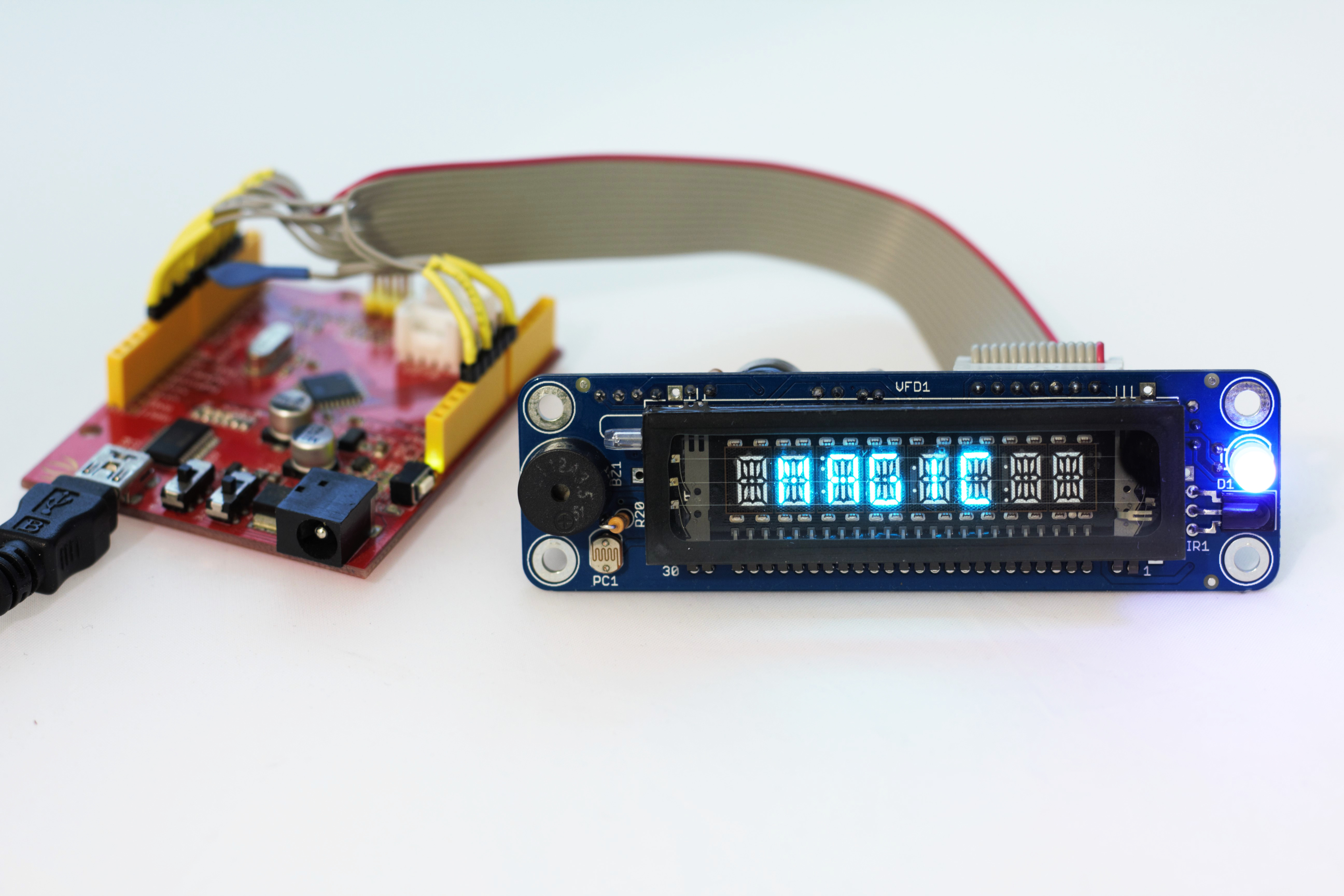
Arduino and MVFD 16S8D Panel in Action
The full test video showing the sketch and the panel in action is given below. In minimalistic configuration (only VFD glass is functional) only 6 wires would be needed (+5VDC, GND, DI, CLOCK, CHIP_SELECT, SHUTDOWN) so some Arduino’s GPIO pins could be freed up.
Firmware:
3. IR Lib
Hardware:
1. Magictale VFD 16S8D Panel Gerber files Rev2.0
2. Magictale VFD 16S8D Panel Eagle files Rev2.0
3. Magictale VFD 16S8D Panel PCBA SketchUp 3D Model Rev2.0
4. Magictale VFD 16S8D Panel Component 3D Models Rev2.0
5. Magictale VFD 16S8D Panel BOM (Bill Of Materials) Rev2.0


Leave a Reply
You must be logged in to post a comment.