


This time our task was to build a Quiz System (also known as ‘Quiz Buzzer’ or ‘Quiz Show’). The real challenge was in meeting two major requirements: being really inexpensive and looking attractive and ‘factory-made’ at the same time as the project was intended for use in elementary school. To our surprise, it became almost next to impossible: when it comes to a pushbutton combined with a bulb or a LED, large enough to be pushed with a palm the price climbs unjustifiably high even for a single button. Given that our project was envisaged to be used by up to six participants the overall cost per unit looked really bleak. And vice versa, cheap (or at least affordable) buttons available at online electronic shops looked too simple or even ugly. That is why we turned our attention to doorbells hoping to find big and reliable buttons. Again, without any success as there is a tendency to shift to wireless doorbells because apparently selling just plain buttons is not a profitable business anymore. We began wandering around visiting numerous local shops looking for something that could work as a pushbutton. And all of a sudden a battery powered wall light in a Chinese shop caught our attention – it looked like a button but at the same time it had a round dome which was illuminated by a bulb just like we needed! But most importantly it had a price tag of just $2! The only problem was that it acted as ‘push and hold’ instead of just ‘push’. In other words, first push switches the light on and in order to switch the light off it has to be pushed again. We decided to take a risk and bought one light to see whether is was possible to convert it to a ‘pushbutton’. As it turned out it was an easy task to do the modification so we rushed and got five more as it is shown on the picture below.
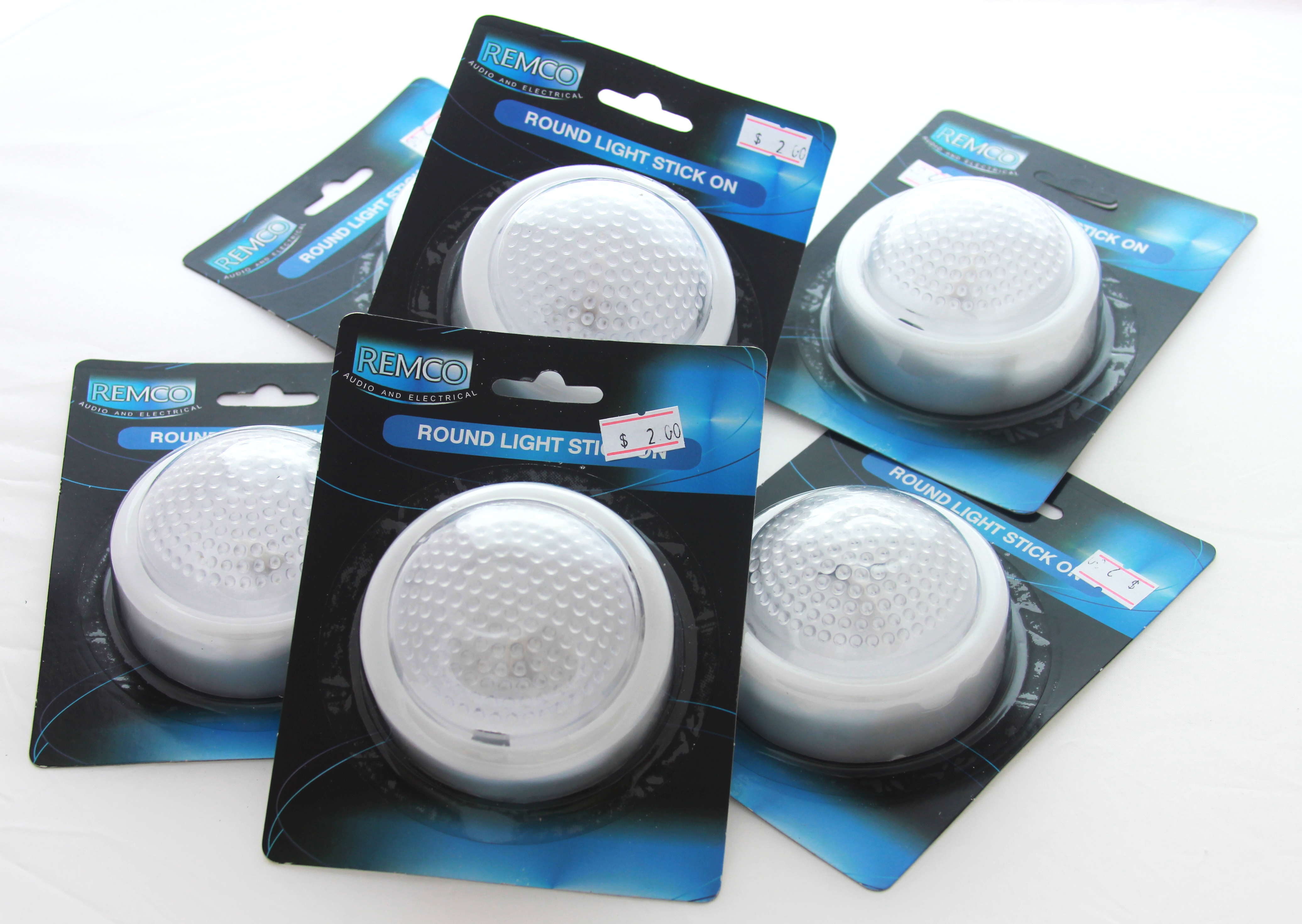
Round Lights From Chinese Shop
And then it was just a matter of replacing bulbs with LEDs and wiring buttons and LEDs to Arduino board. The table below shows the total cost of materials and parts under $47 which is pretty good as the initial requirement was to stay just below $100. Besides, there are still ways to bring down the total cost even more.
| Part | Supplier | Unit Price, A$ | Count | Extended Price, A$ |
|---|---|---|---|---|
| Arduino Mega2560 R3 | Aliexpress/Ebay |
13.00
|
1 |
13.00
|
| Mega Enclosure – Blue (PRT-11985) | Sparkfun |
12.95
|
1 |
12.95
|
| Push button (modified wall light) | Local Chinese shop |
2.00
|
6 |
12.00
|
| Huckup Wire Pack (WH3025) | Jaycar Electronics |
4.95
|
1 |
4.95
|
| 1.5mm Heatshrink Tubing (WH5570) | Jaycar Electronics |
1.45
|
1 |
1.45
|
| Red/Orange/Green/Blue Through Hole 3mm LED >=2700 mcd | Digikey Electronis |
0.31
|
6 |
1.86
|
| Through Hole 180 Ohm Resistor 0.125W | Digikey Electronis |
0.09
|
6 |
0.54
|
|
Total
|
46.75
|
|||
LEDs and buttons wiring up is rather asсetic and doesn’t require advanced soldering skills. LEDs are connected as common cathode so they share common ground with buttons. Each pushbutton needs three wires, one for button, one for LEDs and one for ground. The given example uses Arduino Mega2560 w which is a little bit overkill for this project and technically speaking virtually any other Arduino board can be used with minimum changes to the wiring up.
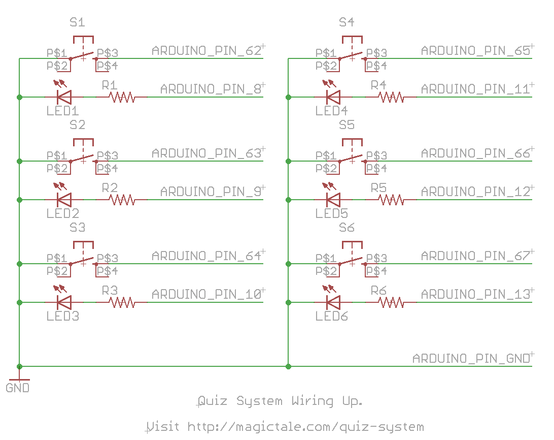
Quiz System Wiring Up
The Arduino sketch provided below shows that the application is really simple: it initialises 6 pins in PWM mode to control LEDs and 6 pins in input mode to read button states. Any change on button inputs triggers an interrupt so that it allows to handle all six buttons independently and without priorities, all users are given equal opportunities. Upon bootup the system enters demo mode when all buttons are lit up sequentially and any button press toggles the gaming mode. In gaming mode a system first waits for a button press. Button which happens to be hit first is illuminated for a few second and the the system is ready for the next round.
/*
QuizSystem.c - automated quiz system for six participants

Copyright (c) 2014 Dmitry Pakhomenko.
dmitryp@magictale.com
http://magictale.com

This code is in the public domain.
*/

#define BTN_1 62	//PK0 PCINT16
#define BTN_2 63	//PK1 PCINT17
#define BTN_3 64	//PK2 PCINT18
#define BTN_4 65	//PK3 PCINT19
#define BTN_5 66	//PK4 PCINT20
#define BTN_6 67	//PK5 PCINT21

#define LED_1 8
#define LED_2 9
#define LED_3 10
#define LED_4 11
#define LED_5 12
#define LED_6 13

const char PRODUCT_NAME[] PROGMEM = "QuizSystem";
const char SPACE_CHAR[] PROGMEM = " ";
const char FIRMWARE_REV[] PROGMEM = "V1.0";
const char FIRMWARE_DATE[] PROGMEM = "22.07.14";
const char COMPANY_URL[] PROGMEM = "http://magictale.com";
const char BTN_PREFIX[] PROGMEM = "BTN: ";
const char INITIAL_STATE[] PROGMEM = "INITIAL STATE";

#define MAIN_LOOP_DELAY 2000
#define SECONDS_IN_SHOWING_RESULTS_STATE 5 * 5 //ToDo: not really in seconds at the moment...

enum enum_SysState
{
sysSelfTest,
sysInitial,
sysQuiz,
sysShowResult,
sysFailure
};

volatile uint8_t sysState;        //current system state (mode)
volatile uint8_t initStateTimer;  //seconds remaining before going to back to initial state
volatile uint8_t btnTriggered;    //flag indicates that a button press was detected
volatile uint8_t btnReg;          //button register;
volatile uint8_t testState;

void serialEvent()
{
while (Serial.available() > 0)
{
//dump the received byte for now
Serial.read();
}
}

void initLEDs()
{
analogWrite(LED_1, 0);
analogWrite(LED_2, 0);
analogWrite(LED_3, 0);
analogWrite(LED_4, 0);
analogWrite(LED_5, 0);
analogWrite(LED_6, 0);
}

void setup()
{
analogReference(DEFAULT);

//Set up 6 button inputs with pullup resistors
pinMode(BTN_1, INPUT_PULLUP);
pinMode(BTN_2, INPUT_PULLUP);
pinMode(BTN_3, INPUT_PULLUP);
pinMode(BTN_4, INPUT_PULLUP);
pinMode(BTN_5, INPUT_PULLUP);
pinMode(BTN_6, INPUT_PULLUP);

//Enable interrupts for buttons
PCICR |= _BV(PCIE2);
PCMSK2 |= _BV(PCINT16);
PCMSK2 |= _BV(PCINT17);
PCMSK2 |= _BV(PCINT18);
PCMSK2 |= _BV(PCINT19);
PCMSK2 |= _BV(PCINT20);
PCMSK2 |= _BV(PCINT21);

pinMode(LED_1, OUTPUT);
pinMode(LED_2, OUTPUT);
pinMode(LED_3, OUTPUT);
pinMode(LED_4, OUTPUT);
pinMode(LED_5, OUTPUT);
pinMode(LED_6, OUTPUT);

initLEDs();

sysState = sysSelfTest;

Serial.begin(57600);

Serial.print(reinterpret_cast<const __FlashStringHelper *>(PRODUCT_NAME));
Serial.print(reinterpret_cast<const __FlashStringHelper *>(SPACE_CHAR));
Serial.print(reinterpret_cast<const __FlashStringHelper *>(FIRMWARE_REV));
Serial.print(reinterpret_cast<const __FlashStringHelper *>(SPACE_CHAR));
Serial.println(reinterpret_cast<const __FlashStringHelper *>(FIRMWARE_DATE));
Serial.println(reinterpret_cast<const __FlashStringHelper *>(COMPANY_URL));

initStateTimer = 0;
btnTriggered = false;
testState = 0;
}

void handleBtnPress()
{
Serial.print(reinterpret_cast<const __FlashStringHelper *>(BTN_PREFIX));
Serial.println(btnReg, BIN);

if ((btnReg) & 0x1) digitalWrite(LED_6, HIGH);
else if ((btnReg >> 1) & 0x1) digitalWrite(LED_5, HIGH);
else if ((btnReg >> 2) & 0x1) digitalWrite(LED_4, HIGH);
else if ((btnReg >> 3) & 0x1) digitalWrite(LED_3, HIGH);
else if ((btnReg >> 4) & 0x1) digitalWrite(LED_2, HIGH);
else if ((btnReg >> 5) & 0x1) digitalWrite(LED_1, HIGH);
}

void demo()
{
while (1)
{
for (uint8_t pwm = 0; pwm < 255; pwm++)
{
initLEDs();

if (testState == 0) analogWrite(LED_1, pwm);
else if (testState == 1) analogWrite(LED_2, pwm);
else if (testState == 2) analogWrite(LED_3, pwm);
else if (testState == 3) analogWrite(LED_4, pwm);
else if (testState == 4) analogWrite(LED_5, pwm);
else if (testState == 5) analogWrite(LED_6, pwm);
else if (testState == 6)
{
analogWrite(LED_1, pwm);
analogWrite(LED_2, pwm);
analogWrite(LED_3, pwm);
analogWrite(LED_4, pwm);
analogWrite(LED_5, pwm);
analogWrite(LED_6, pwm);
}
delay(1);
}

for (uint8_t pwm = 255; pwm > 0; pwm--)
{
initLEDs();

if (testState == 0) analogWrite(LED_1, pwm);
else if (testState == 1) analogWrite(LED_2, pwm);
else if (testState == 2) analogWrite(LED_3, pwm);
else if (testState == 3) analogWrite(LED_4, pwm);
else if (testState == 4) analogWrite(LED_5, pwm);
else if (testState == 5) analogWrite(LED_6, pwm);
else if (testState == 6)
{
analogWrite(LED_1, pwm);
analogWrite(LED_2, pwm);
analogWrite(LED_3, pwm);
analogWrite(LED_4, pwm);
analogWrite(LED_5, pwm);
analogWrite(LED_6, pwm);
}
delay(1);
}

testState++;
if (testState > 6)
{
testState = 0;
break;
}
}
}

void loop()
{
if (millis() % MAIN_LOOP_DELAY == 0)
{
if (initStateTimer != 0) initStateTimer--;
}

switch (sysState)
{
case sysSelfTest:
{
demo();
break;
}

case sysQuiz:
{

break;
}

case sysShowResult:
{

if (btnTriggered)
{
handleBtnPress();
btnTriggered = false;
}

if (initStateTimer == 0)
{
sysState = sysQuiz;
initLEDs();
Serial.println(reinterpret_cast<const __FlashStringHelper *>(INITIAL_STATE));

}
}
break;

default:
;

}
}

ISR(PCINT2_vect)
{
cli();

btnReg = 0x7F & ~*portInputRegister(digitalPinToPort(BTN_1));

if (sysState == sysQuiz)
{
sysState = sysShowResult;
initStateTimer = SECONDS_IN_SHOWING_RESULTS_STATE;
btnTriggered = true;

}else if (sysState == sysSelfTest)
{
sysState = sysQuiz;
initLEDs();
}
sei();
}
The video below shows the process of building and Quiz System in action:
What is more important, the system has plenty of resources unused and this project can be looked at as a template for more advanced and sophisticated designs. For example, it can be integrated with a PC via USB interface so that the device can control Power Point presentations for instance which would navigate to certain pages depending on user input. Another possible enhancement is addition of a RC interface for master control or a small graphic display to indicate winner number – all those small things which would make children interested in gaming process or maybe even in electronics & programming.


Leave a Reply
You must be logged in to post a comment.