


Recently, after attending Ability-Maker-Meetup we were inspired by a group of friendly and openminded people with vision, passion, creativity and tremendous variety of skillsets. The people who share the same goal – to help those in need and with limited mobility by making openhardware things making hard lives of disabled people a bit easier and brighter. And by having design files free and open to anybody it would significantly reduce the final price of a product, increase its flexibility and make it possible to integrate with more platforms and other projects. It would also help to bring back to Earth people who totally lost sense of reality, people who sell primitive things for absolutely ridiculous prices like these. No wonder that we soon found ourselves being inadvertently involved into one of the projects.
On a surface the project sounded really simple – design a wireless button with tactile sensation for scanning software to communicate to a tablet PC for just under $40. However, this quickly led to conflicting requirements. First of all, a wireless interface needs battery and the last thing you want is to put a wireless button on charge every night. Especially if you are not as mobile as an average person. Which means that we need an ultralow power consumption and it really leaves us with two options: low energy Bluetooth (aka Bluetooth 4, aka BLE) and Zigbee. Most mobile devices don’t have Zigbee radios and it is rather exotic piece of hardware. Yes, there are Zigbee dongles in micro SD card form factor so potentially it is possible to make, for instance, a mobile device Zigbee enabled at the cost of not having external flash memory. Also, this solution would require specific drivers to support Zigbee connectivity. On the other hand, most mobile platforms have inbuilt Bluetooth radios. Not all of them are compatible with BLE standard, however, and it is BLE only that can give us truly low power consumption allowing to give enough juice to a button for months if not a year or two and even a coin battery would have enough capacity for this.
Another thing to consider is development effort on a mobile platform side, to be more specific, absence of such. Otherwise the development time for one driver would be multiplied by the number of mobile platforms that ought to be supported. In the world of USB the most obvious choice would be HID. There are also implementations of HID over Bluetooth and if we choose this one there won’t be need for any custom made driver at all. It is worth mentioning, however, that not all mobile platforms with BLE stack have HID support – this problem could be solved by using another (even user-specific) Bluetooth 4 profile and implementing custom driver on a mobile platform. But how to deal with mobile platforms that don’t support Bluetooth 4? Currently there are solutions on the market which are both Bluetooth 2 and Bluetooth 4 compatible but such a compatibility comes at a price: they are more expensive and more power hungry as in essence they have to accommodate two radios so by using them we would shoot ourselves in a foot again with need to recharge/replace batteries every so often. So our choice would be to have a pure Bluetooth 4 button only and design and distribute separately a ‘Bluetooth-4-to-whatever’ translator that is powered by a wall adapter. This translator, however, would be out of scope of this article.
We also need to keep in mind that instead of using specialised chips we actually need an FCC certified module with fixed antenna. That way we can safely avoid intricacies of RF designing (which is more like black magic than actual designing) and possible customers’ accusations like ‘your device can cause harm to a live tissue by its electromagnetic radiation’.
Summarising the requirements and ‘nice to have’ features, there is the list of criteria for a potential BLE module that we will be going to look for:
- An FCC certified Bluetooth 4 (BLE) module with fixed antenna;
- Support of HID BT profile;
- Handsolderable pins (no QFN, BGA like footprints, it is a DIY project after all) yet compact form factor;
- Reasonable price (less than $20);
- Minimum power consumption, capable of entering deep sleep modes and waking up by external interrupts;
- Voltage supply in the vicinity of 2…3V to be powered directly off a 3V coin battery and therefore avoiding using of extra DC-DC converter;
- Configurable/programmable which would allow not to use external microprocessor and bring down the cost and power usage even more;
- No need in external debugger to reconfigure/reprogram the module;
- Opensource or free development environment (yes, dear Texas Instruments, we know your shallow jokes);
- The module must be futureproof, or in other words be designed by a company specialising in wireless modules with proper technical support, definitive end of life/end of support terms and so on. Not like the toys from Adafruit;
As a result of our search the best candidate matching our requirement would be BLE112-A-V1 module for the retail price of $15.66 from Digikey as it is shown on the picture below:
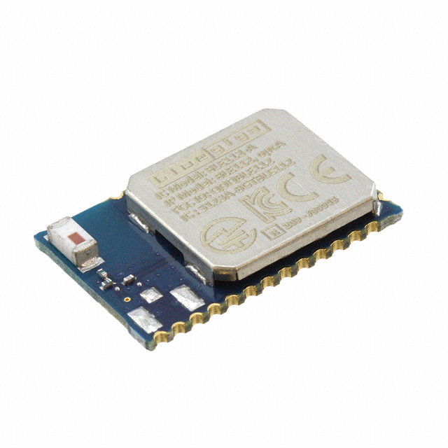
BLE112-A-V1 Module
At a first glance the module looks amazing: a 8051 processor as a core which makes it possible to write conventional C code and upload it to the module, three (!) ways of firmware upload – either over USB interface, OTA (over the air) or by means of CC-Debugger (oh no, the chip is made by Texas Instruments, a notorious cheater with CC2430 Zigbee chip, overpriced development environment for it, buggy and unstable Zigbee stack without access to source code and cowardly abandoned support). However, after a closer look it is seen that there is no way to write in C when not using an external host processor and the code has to be written is a BASIC-like compilable script invented by Bluegiga. As for the firmware uploads, once USB is enabled it uses so much power that it defeats the whole purpose of low energy Bluetooth and OTA works only if certain conditions are met so it really leaves us with the only way – CC-debugger (which would cost us some additional money). Apart from these inconveniences everything else looks quite reasonable so we are going to use the module as a cornerstone for our project.
The fist revision of circuit diagram is given below. The module and capacitors C1...C4 are part of the reference design provided by the BLE112 datasheet. The power source is a CR2032 coin battery with J2 jumper allowing to measure current consumption during development cycle. Instead of just one button there are four tactile switches SW1...SW4 which can be programmed to the same logical button. There is also an option to connect an external, more durable button if needed using P2 EXT_BTN connector. Resistors R2...R6 provide weak pull-up when a module is in deep sleep mode and thus making sure that the microprocessor’s inputs are in definitive states. If no external button is used, R6 must not be loaded. Connector P1 SER_DBG is used for serial debug output during development. An LED LED1 can be used as an optional visual indication of a button press and it is connected to a GPIO capable of sourcing up to 20 mA. However, given that we have very tight power budget, we are using a 2mA LED with high resistance in series. J1 provides a way to disconnect LED altogether is longer battery life is needed. Or alternatively, both LED1 and R1 can be unloaded. P3 CC_Debugger allows to connect CC-Debugger and upload a custom designed application.
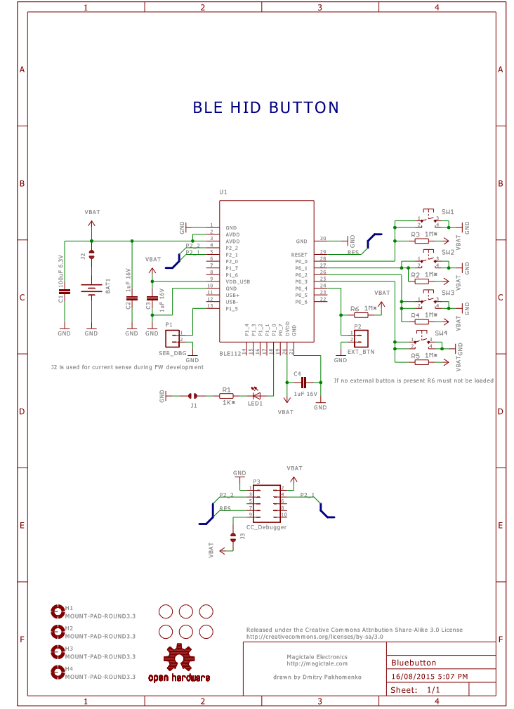
Blueutton Circuit Diagram Rev.1.0
A PCB layout is done on 2 layer 50x50mm blanks to take advantage of budget PCB manufacturing service by ITeadStudio. On the top side the buttons are the most extending mechanical parts to accommodate a big round plastic lid on top covering all four buttons. The bulky components are residing on the bottom side. Both top and bottom sides are filled with copper polygons connected to ground with cut-off window near module’s antenna area as per datasheet layout guidance. The two ground plains are stitched with vias across the cut-off’s perimeter to minimise noise and electromagnetic emission as much as possible. Our initial intention was to squeeze everything into Keyfob case but after thorough consideration the idea was rejected because of the really small rubber button which would be difficult to press so the decision was to make a 3D printed case specifically designed for our PCB.
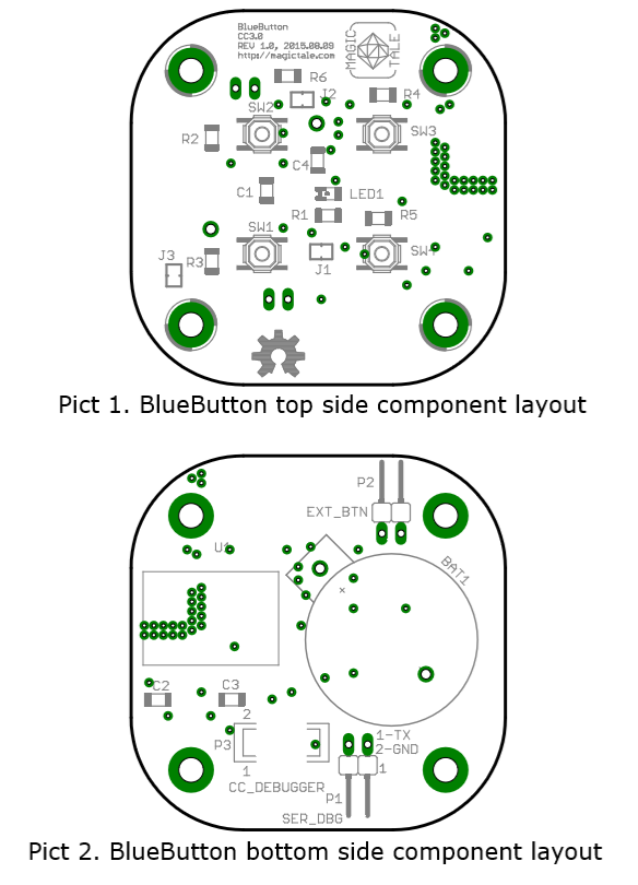
BlueButton Component Layout Rev 1.0
A 3D model of the PCB is provided below.
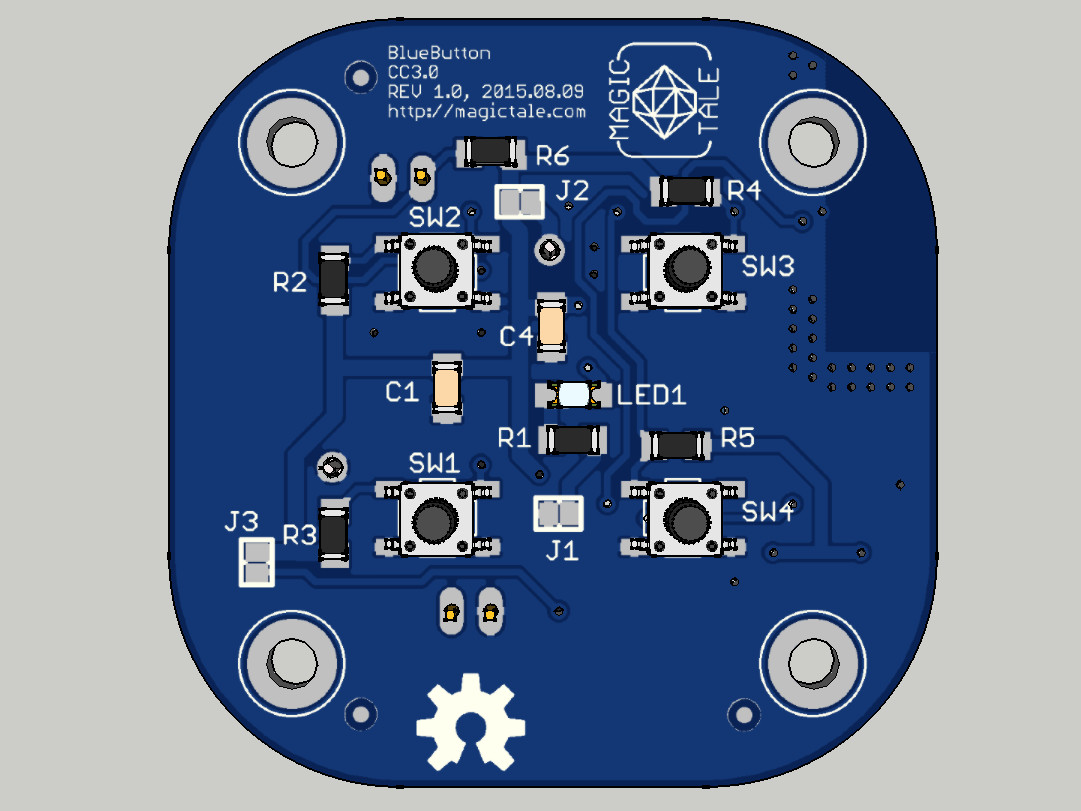
BlueButton PCBA 3DModel Top View
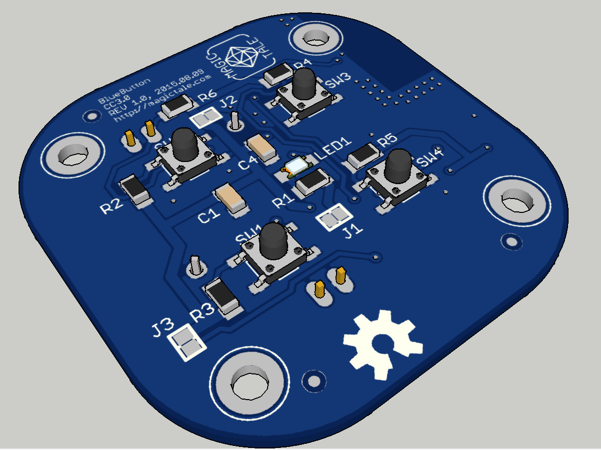
BlueButton PCBA 3D Model Top Iso View
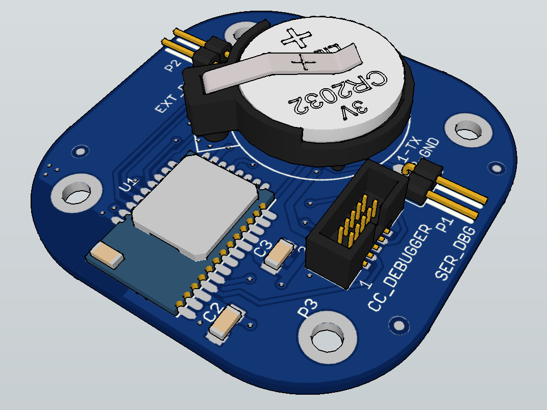
BlueButton PCBA 3D Model Bottom Iso View
Upon arrival of the manufactured PCBs we will be assembling the first prototype and testing our custom made scripts. Also we will be designing a simple enclosure model which then most probably will be 3D printed. All this will be posted in the next article.
Downloads:
1. BlueButton Gerber files Rev1.0
2. BlueButton Eagle files Rev1.0
3. BlueButton PCBA SketchUp 3D Model Rev1.0


Leave a Reply
You must be logged in to post a comment.