This post is a continuation of our endeavour to enhance USB Host 2.0 for Arduino library making a particular focus on SPP Bluetooth profile and Luminardo’s ability to initiate connection to a remote Bluetooth SPP-aware hardware. Last time it has been described what had to be changed in the library in order for Luminardo to start pairing sequence. Today we are going to progress further and discover what else has to be done. But before we proceed first we need do to some preparations to make sure that we have tools and documentation handy. Note, that this post doesn’t set a goal to make a complete Bluetooth guide, it is rather an example which demostrates where to start and how to learn in order to solve a problem related to BT stack.
First of all, we would need Bluetooth core specification. It sounds obvious but strangely enough it is not such as straightforward as it seems: there are several core specifications with version numbers ranging from 2.0 to 4.1 not to mention numerous specification ‘addendums’. A brief investigation reveals that the library is built around rev.4.0 and the appropriate document location would be here. Two more documents would be also extremely useful: SPP Specification ver.1.2 and GSM 07.10 Specification.
Secondly, having a real working system (e.g. two Bluetooth SPP-aware devices) as a reference point can significantly simplify the learning process as all the above mentioned documents are really difficult to read and even more difficult to comprehend. Being able to watch the actual data exchange is a must. Using a PC with Windows OS gives virtually nothing as the Bluetooth stack is an integral part of OS kernel and apparently there is no way to sniff or log Bluetooth packets. What is even worse, different versions of Windows use completely different Bluetooth stacks but all of them are black boxes – nobody knows what is happening inside. On the other hand, Linux and its Bluetooth stack have everything in place for efficient packet debuging and troubleshooting. Out team used Lubuntu with pre-installed Bluez package. Hovewer, to log packets one more package must be installed: bluez-hcidump. In our environment all that needed to be done to install it was apt-get install bluez-hcidump in command line.
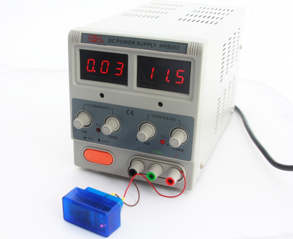
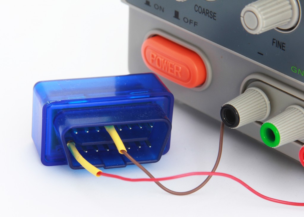
And finally we would need a device to connect to. It could be another PC or laptor with Bluetooth adapter or an ELM327 adapter. In latter case an adapter must be powered up as at this stage there is no need in physical communication with car’s bus and it is enough to apply supply voltage only. Also it is extremely inconvenient to run experiments in a car be it inside a dark garage or a parking spot, a home lab would be a better place. Any 12VDC power supply capable of delivering at least 100 mA will do. During our tests we used a bench power supply as shown on the pictures below. Make sure you get polarity right: brown wire is GND, red wire is +12VDC.
Now a significant amount of time must be spent trying to combine knowledge contained in Bluetooth specs, logic contained in SPP.cpp and BTD.cpp files and common sense. It also takes some time to get familiar with bluez-hcidump peculiarities as it offers wide range of options allowing to log in different formats. The specs are written in a very strange way, while reading you keep asking yourself only one question over and over again: what were those guys smoking when they wrote those specs? Information is scattered across not only pages and chapters but different files as well, it is extremely difficult to make sense out of it. They keep jumping from one topic to another, often using lengthy descriptions of an entity or a process while a single picture-example would be worth a thousand words, you need to read the same passage multiple times trying to understand what they meant. What is even worse, the information often looks ambiguous and inconclusive, there is no way to comprehend it fully unless you have a real hardware and library to conduct some experiments to proof or disproof your guesses after reading the spec. The information available in the Internet is surprisingly scarce: apart from the official Bluetooth specs which are easy to understand only for people who wrote them there is basically nothing else. Documentation and forum discussions for Bluez or btstack are only about API and how to use it, the actual implementations of the stacks are not discussed as such or discussed by BT professionals who already has a deep knowledge of the specifications. It looks like everyone considers the stack as a given without actual understanding how and why it works, and those who know about it prefer to keep the knowledge closed, it is really unclear how overcome this vacuum before you know enough to progress further towards the numbered group of Bluetooth guru.
As we already spent significant amount of time here are some facts that came out of our effort:
1. Reversing the role of our device from acceptor to initiator requires rater major redesign of logic resided in SPP.cpp. Format and content of packets sent by initiator is unknown at the moment and yet to be discovered;
2. In order to establish connection to a remote device via SPP it is required to interrogate SDP service to get a port number to connect to;
3. As soon as port number is known, connection to RFComm service should be initiated.
All interactions with SDP and RFComm services are done trough underlying L2CAP interface, for simplicity sake consider it as a backbone transport layer. Before any requests can be sent to either SDP or RFComm services a connection to that service has to be established by means of standard set of L2CAP commands. The order of these commands is important. In most cases if a command is malformed or sent at inappropriate time it will be ignored and no error packet of any kind will be sent which undoubtedly makes troubleshooting more difficult. A typical sequence of establishing connection to an SDP (RFComm or any other) service is given below:
1. Initiator sends CONNECTION REQUEST;
2. Acceptor replies with CONNECTION RESPONSE and shortly after sends CONFIGURATION REQUEST;
3. Initiator replies with CONFIGURATION RESPONSE and shortly after sends CONFIGURATION REQUEST (or the other way around);
4. Acceptor replies with CONFIGURATION RESPONSE – and from this moment connection is established and service specific commands can be sent;
Let’s confirm our theoretical knowledge with real working system. Power up ELM327 then start Bluetooth Manager in Linux, search for available devices and it should detect ELM327 as ‘OBDII’. Pair with it and enter pin ‘1234’ when requested (please refer to user manual of your ELM327 as there could be another value for pin code). Start Linux two consoles and run in first one hcidump command without parameters and in second one hcidump - X -R command. Then go to OBDII’s properties, click ‘Setup’ and select ‘Connect to Serial Port’. You should see data coming in and out logged by hcidump. Here is a portion of data logged by the first console:
< ACL data: handle 43 flags 0x02 dlen 12
    L2CAP(s): Connect req: psm 1 scid 0x0040  //outgoing CONNECTION REQUEST to PSM = 1 (Service Discovery Protocol) from a client with SCID = 0x0040 (Source Channel Identifier, a unique ID of our endpoint or client)
> ACL data: handle 43 flags 0x02 dlen 16
    L2CAP(s): Connect rsp: dcid 0x0040 scid 0x0040 result 0 status 0 //incoming CONNECTION RESPONSE from a remote endpoint with DCID = 0x0040 with result and status set to 0 (success)
      Connection successful
< ACL data: handle 43 flags 0x02 dlen 12
    L2CAP(s): Config req: dcid 0x0040 flags 0x00 clen 0 //outgoing CONFIG REQUEST from our endpoint with config parameters (flags) set to 0
> ACL data: handle 43 flags 0x02 dlen 20
    L2CAP(s): Config req: dcid 0x0040 flags 0x00 clen 8 //incoming CONFIG REQUEST from remote endpoint
      MTU 60
      FlushTO 65535
< ACL data: handle 43 flags 0x02 dlen 18
    L2CAP(s): Config rsp: scid 0x0040 flags 0x00 result 0 clen 4 //outgoing CONFIG RESPONSE from our endpoint
      MTU 60
> ACL data: handle 43 flags 0x02 dlen 18
    L2CAP(s): Config rsp: scid 0x0040 flags 0x00 result 0 clen 4 //incoming CONFIG RESPONSE from remote endpoint
      MTU 48
The second console logs data in raw format and gives opportunity to see actual byte stream. The same portion of data will look like this:
< 0000: 02 2a 20 0c 00 08 00 01  00 02 03 04 00 01 00 40  .* ............@ //outgoing L2CAP CMD CONNECTION REQUEST (0x02 at address 0x0009)
  0010: 00                                                .

> 0000: 02 2a 20 10 00 0c 00 01  00 03 03 08 00 40 00 40  .* ..........@.@ //incoming L2CAP CMD CONNECTION RESPONSE (0x03 at address 0x0009)
  0010: 00 00 00 00 00                                    .....

< 0000: 02 2a 20 0c 00 08 00 01  00 04 04 04 00 40 00 00  .* ..........@.. //outgoing L2CAP CONFIG REQUEST (0x04 at address 0x0009)
  0010: 00                                                .

> 0000: 02 2a 20 14 00 10 00 01  00 04 4c 0c 00 40 00 00  .* .......L..@.. //incoming L2CAP CONFIG REQUEST (0x04 at address 0x0009)
  0010: 00 01 02 3c 00 02 02 ff  ff                       ...<.....

< 0000: 02 2a 20 12 00 0e 00 01  00 05 4c 0a 00 40 00 00  .* .......L..@.. //outgoing L2CAP CONFIG RESPONSE (0x05 at address 0x0009)
  0010: 00 00 00 01 02 3c 00                              .....<.

> 0000: 02 2a 20 12 00 0e 00 01  00 05 04 0a 00 40 00 00  .* ..........@.. //incoming L2CAP CONFIG RESPONSE (0x05 at address 0x0009)
  0010: 00 00 00 01 02 30 00                              .....0.
At this stage it would be worth to get familiar a bit with packet structure and payload. So far there are four packet types: L2CAP CONNECTION REQUEST, L2CAP CONNECTION RESPONSE, L2CAP CONFIG REQUEST and L2CAP CONFIG RESPONSE. All four structures are given below.
=== HCI header ===
02 2a HCI hanle with PB and BC flags
20 0c HCI ACL total data length (it actually specifies total length 0x000C
   according to Bluetooth Core Spec. rev.4.0, Host Controller Interface Functional Spec)
   and be 0C 00 instead of 20 0C but we don't worry about it now - it works for us anyway
00 08 L2CAP payload length
00 01 L2CAP channel ID (0x0001 for ACL-U, please refer to Bluetooth Core Spec. rev.4.0,
  Logical Link Control and Adaptation Protocol Specification, page 54)

00 ??? Unknown byte, it is present neither in spec nor in packets when sent from Arduino/Luminardo.
  Probably a bug in hcidump as the byte is not even accounted by HCI ACL total data length

=== Actual L2CAP command ===
02 L2CAP_CMD_CONNECTION_REQUEST
03 Packet identifier
04 00 Command payload Length
01 00 SDP_PSM
40 00 SCID, Source Channel Identifier
=== HCI header ===
02 2a 20 10 00 0c 00 01  00 - HCI header, as above, please see the L2CAP CONNECTION REQUEST packet structure

=== Actual L2CAP command ===
03 L2CAP_CMD_CONNECTION_RESPONSE
03 Packet identifier
08 00 Command payload length
40 00 DCID (Destination Channel Identifier, in other words, a remote endpoint ID)
40 00 SCID (Source Channel Identifier, in other words, local endpoint ID)
00 00 Result 0 (success)
00 00 No more data
1-st case in our log generated by sniffer
=== HCI header ===
02 2a 20 0c 00 08 00 01 00 - HCI header, as above, please see the L2CAP CONNECTION REQUEST packet structure

=== Actual L2CAP command ===
04 L2CAP_CMD_CONFIG_REQUEST
04 Packet identifier
04 00 Command payload length
40 00 DCID (Destination Channel Identifier, in other words, a remote endpoint ID)
00 00 Flags


2-nd case in our log generated by sniffer
=== HCI header ===
02 2a 20 14 00 10 00 01 00 - HCI header, as above, please see the L2CAP CONNECTION REQUEST packet structure

=== Actual L2CAP command ===
04 L2CAP_CMD_CONFIG_REQUEST
4c Packet identifier
0c 00 Command payload length
40 00 DCID (Destination Channel Identifier, in other words, a remote endpoint ID)
00 00 Flags
01 Config Opt: type = MTU (Maximum Transmission Unit) - Hint
02 Config Opt: length
3c 00 MTU
02 Config Opt: type = Flush Timeout
02 Config Opt: length
ff ff Flush timeout
=== HCI header ===
02 2a 20 12 00 0e 00 01 00 - HCI header, as above, please see the L2CAP CONNECTION REQUEST packet structure

=== Actual L2CAP command ===
05 L2CAP_CMD_CONFIG_RESPONSE
4c Packet identifier
0a 00 Command payload length
40 00 SCID (Source Channel Identifier, in other words, local endpoint ID)
00 00 Flag 0
00 00 Result 0 (success)
01 Config Opt: type = MTU (Maximum Transmission Unit) - Hint
02 Config Opt: length
3c 00 MTU
Now we have a bit of understanding on how to establish connection to SDP service (same applies to RFCom) and we are ready to comminicate with SDP service. What should be done and how to do it will be discussed in our nest post. Stay tuned and ask questions if you have any!


Leave a Reply
You must be logged in to post a comment.