Here is a replica of DefendLineII main unit and GSM/GPS Module fitted in ordinary box for 10 DVDs.
|
|||||||||||||||||||||||||||||||||||||||||||||||||||||||||||||||||||||||||||||||||||||||||||||||||||||||||||||||||||||||||||||||||||||||||||||||||||||||||||||||||||||||||||||||||||||||||||||||||||||||||||||||||||||||||||||||||||||||||||||||||||||||||||||||||||||||||||||||||||||||||||||||||||||||||||||||


Grand Prize Winner (Dec 2012) 
Second Prize Winner (July 2012) 
Unless otherwise stated, this work is licensed under
a Creative Commons Attribution-ShareAlike 3.0 License
If you decide to buy a uCAM JPEG module from Australian company 4d Systems then be extra careful because you may end up with faulty module without any chance to get your money back. The trick is simple: you buy, let’s say, two modules from them. In a couple of weeks your shipment arrives undamaged and untampered (yes, two long weeks to deliver a shipment from Penrith to Sydney, just about 60 km!). You unpack first module, test it and use it in your project. The module works just fine and there is a deceptive feeling that second module should be left intact unless you really need it in your next development cycle or second project. But here is the catch – due to poor quality control (or maybe even absence of it) at the seller’s side your next module might be basically non-functional. The most obvious action is to contact supplier’s support, its email address is conveniently provided on supplier’s website. The only problem is that they ignore your pathetic requests. Of course, this is only because their anti-spam system due to unknown to any human on Earth reasons blocks your and only your message. At the beginning you patiently waiting for a reply, cheerful, full of optimism, confidently thinking that it is just a temporary misunderstanding between you and tremendously custom-oriented 4d Systems. In a few days you begin realising that nobody in support is willing to deal with your annoying issue. To defeat that invincible anti-spam system you decide to submit your request to unreachable and invisible support team via conveniently provided web form. This action requires ‘Order ID’ field to be set – and guess what? – it won’t help their highly productive support team to find out the actual invoice associated with your purchase, they will ask you to send the invoice to them! Moreover, when using the web form, you have no means to attach any file, for instance, a snapshot or a picture just to prove that the item is faulty indeed. The only way is upload you file somewhere else and embed a link to it into message body. And when the support eventually contacts you there are very good chances that you already lost your money and time because according to their fair replacement policy you can exchange a faulty item only within 3 (three) months since the date of purchasing. It is like a bottle of milk with its ‘Best before’ and ‘Use by’ dates – 4d Systems can’t guarantee that in three months your camera module won’t go off like that bottle of milk! That is really funny, well done, guys! They way they communicate to their customers is also worth noticing:
No regrets, no apologies, only ambitions and very useful recommendations what customer MUST do to avoid problems CREATED BY THE MANUFACTURER-SUPPLIER. Also the company tends to blame its customers for incorrectly working hardware. Speaking of uCAM-TTL module, 4d Systems forum is full of admin supportive posts saying that ‘your host controller is not handling camera’s packets as it should that is why you are under impression that the camera is faulty’. In other words, ‘your firmware is buggy and therefore it can’t work with our beautiful camera’. Look who is talking, guys! ‘uCAM-Tool’ software is really worth admiring. This tool allows to test your camera eliminating chances that your own code may not entirely follow the spec and you may deceptively blame the camera. But there is a group box ‘OV528 Jpeg problem’ on the main form with the options ‘OV529/Ignore’ and ‘Fix’ meaning that the camera does have some flows. And if you are unlucky enough to check ‘Video Mode’ in ‘Snapshot’ groupbox then you are doomed – there is no way to abort communication between the tool and the camera, you have to kill the process in Task Manager! And that is how our faulty camera behaves, please refer to the picture below. There are six snapshots for JPEG, 16-bit color, 8-bit color and 8-bit greyscale modes – all of them indicate a problem and it is obvious that this problem is not related to communication protocol nor JPEG compression – there is something wrong with the imaging sensor.
The conclusion is simple. Looks like it is worth integrating the project with LinkSprite JPEG Color Camera. Just to not be dependable on one supplier and to have more options to choose from. Stay tuned! Here is a demonstration of DefendLineII project working together with GSM/GPS Module. Module software support includes GSM module library and an example of its typical usage for ATMega microprocessor family written in C/C++. The logic of interaction with SIM900D modem is enclosed in
On top of this logic more meaningful commands are implemented such as:
Also there are two sets of methods, for sending data via HTTP and TCP protocols. The first set utilises HTTP related AT commands, it hides a lot of things from end user and therefore much simpler for use. However, it does not allow to define arbitrary HTTP header and as a consequence, there is no way to send MIME-encoded POST requests and therefore no way for sending binary data such as pictures. In addition, the the commands do not provide functionality to set HTTP parameters separately and it is entirely user application responsibility to do URL-encoding. There is also no way to get response HTTP header fields, they are hidden by the modem. Yet this is fairly simple way to make HTTP requests by means of dedicated HTTP AT commands, the commands provide the following functionality:
The second group of methods facilitates sending/receiving data over TCP/UDP protocols and HTTP request might be generated on top of TCP. This way is more complex, it requires more efforts on user application side and utilises more RAM for intermediate buffer. At the same time it gives you all flexibility you need without limitations in number of parameters and binary data length as requests are sent by chunks. The following functionality is provided:
Let’s take a closer look at the list of commands starting from low-level layer:
A list of auxiliary methods is given below:
Methods for SMS functionality:
A list of methods for making HTTP connections by means of embedded HTTP AT commands:
A list of methods for making HTTP connections over TCP AT commands (which is primarily used by the example):
To be continued… Downloads:Components are soldered on both sides of the PCB. Only components that need to provide the required functionality should be soldered. Depending on your situation, some components such as CONN1, CONN2, CONN4, CONN5, L1 etc can be soldered on either side of the board. There is no strict sequence for soldering but U1 should be probably installed first as it has many pins along three sides and should be positioned very precisely. The most challenging component to be soldered is D1 due to its smallest pin pitch (and which is actually used to protect SIM interface lines from ESD). If you can’t solder it then don’t do it – you will just need to take more ESD precautions when replacing SIM card. PCB component layout for both sides is given below:
Time to begin soldering components. But before make sure that you have the following tools and materials get ready: solder iron with temperature control or soldering station, solder, solder wick, mutimeter, tweezers. We highly recommend to use solder paste in syringe packaging which will significantly improve the quality of your soldering. Based on our own experience we would advise to get SMD291NL that is available in Digikey.com, inexpensive and the the same time gives noticeable good results. To make things even more easier it would be also useful to have a magnifying glass and plenty of natural light (preferably daylight). As many components are ESD sensitive it would be worth taking anti-static protection precautions. The tip would to be well earthed (grounded) in any circumstances when handling CMOS components, not only soldering them. Downloads:The minimum set of components for GSM functionality and external 3.4V 2A power supply is given below:
In case of using external 12V an onboard DC-DC converter will require the following components to be soldered as well:
Set of components for GPS functionality is given below:
Set of components required for onboard power 3.3V supply for GPS receiver (if no external 3.3V voltage is present):
Set of components required for external microphone connection:
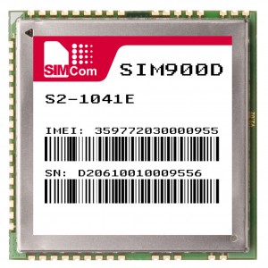
The GSM part is based on SIM900D GSM module. SIM300DZ has the same pin layout and designation so it might be used as a replacement of SIM900D. Q1 transistor, R2, R3 and R4 resistors are used to drive LED1 ‘NET LIGHT’ which indicates module networking status. CONN4 is a SMT antenna connector. Q2 transistor and R8, R9 resistors facilitate module powering on and off via PWRK line. C4, C5, C6 capacitors, L2 and L3 inductors and CONN9 are optional for external microphone connection. Optional CONN3 connector is for debugging and firmware upgrade purposes. CONN7 SIM CARD holder is connected to the module through matching the impedance R5, R6 and R7 resistors and D1 for ESD protection. Optional CONN6 and CONN8 are for Li-Ion battery and battery charger accodingly. The modem is connected to the host controller via CONN1 connector with the following pin designations: TX, RX, RTS, CTS are used for serial communication, STAT is used to detect whether the module is switched on or off, PWRK is for the actuall switching on and off, RESG is used for Copernicus GPS module reset. The GPS part is based on Copernicus module. It also has SMT connector CONN5 for GPS antenna and CONN2 for connection to the second serial port on a host controller.The module might be set to power down mode via STBY line. There are a few options for powering the device. First of all, 3.4V DC 2A could be supplied through pins 8, 10 of CONN1. The typical voltage is usually 3.3 but it is just not enough for SIM900D, the critical level is 3.4V so if you have voltage of this level on your host controller then use this option. Just keep in mind that SIM900D peak current consuption is 2A. In this case the power selector JP1, JP2 should be shorted with jumpers at 1-2 pins. The second option is to use 12V external voltage then U3 regulator, C2, C3, D2, L1, R10, R11 and FB1 elements should be soldered. It provides SIM900D with optimum 3.7V. In this case 1-2 pins of JP3 and 2-3 of JP1, JP2 must be closed with jumpers. Now there is still a need in 3.3V for the GPS chip, it could be supplied via pin 6 of CONN2 connector or provided by soldering U4, C9, L4 and C10 components, it will give 3.3V at 150 mA which could be used somewhere else. In the latter case the only required input voltage to be provided externally will be 12V. The project’s circuit diagram is given below:
Note:Circuit diagrams are licensed under a Creative Commons Attribution Share-Alike license,which allows for both personal and commercial derivative works,as long as they credit ‘AVR Magictale Projects’ and release their designs under the same license. This module is a cost effective and flexible solution providing your own microcontroller with wireless Internet connectivity, remote controlling via SMS and GPS functionality. As a GSM module either SIM900D or SIM300DZ might be used, some of the most affordable GSM modules currently on the market featuring embedded TCP/IP stack over AT commands so measurement data, pictures, messages etc might be sent directly to TCP servers over the Internet. Moreover, SIM900D comes with HTTP and FTP commands dramatically simplyfing interactions using these protocols. The module is interfaced via serial port and a few extra lines so it needs minimum GPIO to be reserved on a host controller. Optional Copernicus GPS module is a sensitive and low power receiver with a frequency of 5Hz for a position resolution. It requires a separate serial port which could be a software (emulated one) on your side if your microcontroller has only one hardware serial port. Both GPS and GSM chips are fully controllable in terms of power management which allows to switch them on at the moments in time when there is a need and put them in power down mode the rest of the time with only a few uA of current consumption making it very econimical in case of battery power source. The GPS/GSM module PCB is designed to suite as many potential applications as it possible, it has facilities to connect external microphone, Li-Ion battery, external battery charger, has a connector for modem’s debug port and numerous options of module power supply including onboard DC-DC regulator. Only those components that are used need to be soldered means that the module will be tailored for your own needs at a minimal price. The project has an extensive software support, there is a thoroughly tested opensource library and set of examples written in C/C++ for AVR microprocessor family. The code might be enhanced at you own discretion, be fully intergated into your own projects and even ported to another microprocessors. Thank you for your attention and all the best, 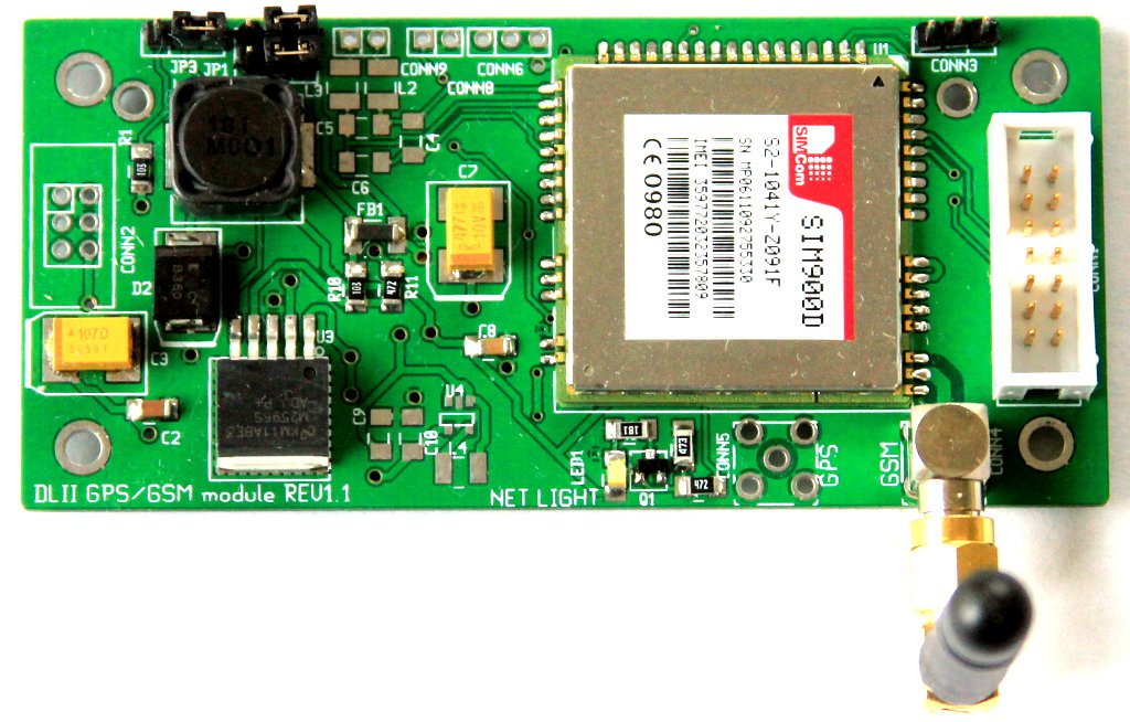 Gps Gsm Module Top View 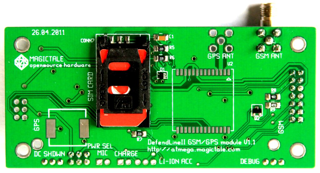 Gps Gsm Module Bottom View GSM/GPS module is a compact, flexible and powerful solution allowing to add GPS functionality and/or Internet connectivity to your own device with minimum effort. The module is designed as one of a few interchangeable transport connectors for DefendLineII project but could be easily mated with any microprocessor based device via serial interface and couple of extra GPIOs (two serial interfaces are needed in case of simultaneous usage of GSM and GPS chips). Depending on the required functionality only those components should be soldered that shall be used to provide that functionality which simplifies assembling process, makes the module cheaper yet still potentially capable of more – you can just add extra components later if you really need. Main unit features:
Please express your interest by posting your comments. It is a known fact that C328 JPEG Serial Camera has been discontinued and not available on the market anymore. But there is a replacement called uCam-TTL Serial JPEG Camera module which is currently being produced and sold by Australian company called 4D Systems. The camera has the same QV7640 image sensor, serial interface and command set which makes it compatible with its predecessor. The module draws the same 60mA at 3.3V DC. Despite it is priced at $59 which is a little bit more expensive in comparison with C328, it has more impressive optics and even lens cover, please see the photo below:  uCAM-TTL Camera Module But even though the module has the same connector it has totally different pinouts, so check the following table below carefully and make all necessary modifications to your cable before connecting to DefendLineII CONN3 serial header:
Camera’s datasheet is available here: uCAM-TTL datasheet The camera and DefendLineII connected together:  DefendLineII and uTTL CAM Module Previous article: DefendLineII. C328 JPEG Colour Camera Integration; Additional info: DefendLineII Kit; |
|||||||||||||||||||||||||||||||||||||||||||||||||||||||||||||||||||||||||||||||||||||||||||||||||||||||||||||||||||||||||||||||||||||||||||||||||||||||||||||||||||||||||||||||||||||||||||||||||||||||||||||||||||||||||||||||||||||||||||||||||||||||||||||||||||||||||||||||||||||||||||||||||||||||||||||||
|
Copyright © 2025 Magictale Electronics - All Rights Reserved |
|||||||||||||||||||||||||||||||||||||||||||||||||||||||||||||||||||||||||||||||||||||||||||||||||||||||||||||||||||||||||||||||||||||||||||||||||||||||||||||||||||||||||||||||||||||||||||||||||||||||||||||||||||||||||||||||||||||||||||||||||||||||||||||||||||||||||||||||||||||||||||||||||||||||||||||||