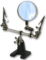
DefendLineII PCB will be distributed in three kits: just a PCB, without any components, a pre-assembled PCB with just ATMega1280, FT232BL, DS1621, PCF8563, MicroSD connector, crystals, ISP10 header and a few resistors/capacitors soldered and fully assembled with all components soldered. If you decided to solder component by yourself then we hope you will find these recommendations useful. The most challenging task is to solder 100-pin ATMega1280 with pin pitch = 0.4 mm. You must be heard many times that it is impossible to solder such chips manually? In reality it is not as scary as it looks – you just need to have certain set of ordinary tools, good soldering skills and patience. First of all, you will need a Clamp tool with magnifier. If could be found in many online stores, we ordered it in Farnell. That is how the magnifier looks like:
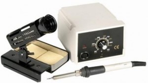
Secondly, you will need not just a soldering iron but a soldering station. It does not have to be an expensive one – something like Duratech TS1560 will be just enough, here is how the station looks:
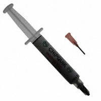
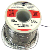
And finally, you will need solder paste in syringe packaging, an invaluable ingredient for soldering/rework processes. We put
SMD291NL to a test, the item was purchased in Digikey and got quite satisfying results. The package filled with soldering paste looks like that:
Now we are ready to solder the chip. Set up the soldering iron temperature to about 350 degrees Celsius (~660 degrees Fahrenheit), place the PCB of a desk in front of you. Make sure that the PCB is laying horizontally and you have enough light, (sunlight is preferable but not mandatory). Using the syringe apply soldering paste generously to cover all pads. Remove the chip from its packaging and carefully place it on the board aligning its pins along the pads. Pay a special attention to the chip’s orientation – it may look differently under the light from different directions – make sure that you pinpointed first pin correctly. Look at the chip through a magnifier – it will reveal possible problematic areas which would left unnoticed otherwise. Finally, all pins should be within pad areas without any overlapping. Solder one outer pin of any of four pin rows while gently holding the chip – either with help of fingers or tweezers. Check the results through the magnifier again. Correct chip alignment if it is necessary and solder another outer pin located diagonally from the first one. Check the results again. Solder the rest of pins. Keep in mind that you do not have to see a pin on a pad with great details – when a pin is soldered, the shape of pad is not flat anymore and it begins to reflect sunlight differently, so it is clearly visible which pins have been soldered and which have been not done yet.
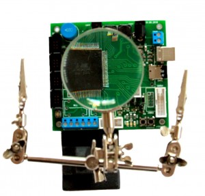
When the process is completed you should have something like this:
Previous article: DefendLineII. Circuit Diagram;
Next article: DefendLineII. Flashing bootloader;
Additional info: DefendLineII Kit;



Leave a Reply
You must be logged in to post a comment.