


The heart of the unit is CPU ATMega1280 microprocessor running at 14.7456 MHz (Y3 crystal). This frequency provides required accuracy to clock serial communications at 57600/115200 bps between the unit and external devices such as PC, GPS module, GPRS modem, JPEG cameras etc. The ATMega1280 processor has four hardware serial ports facilitating simultaneous interactions with a few serial-aware modules. CONN19 is a standard JTAG header, CONN20 is a standard ISP10 header, its pinouts is fully compatible with very popular among hobbists USBTiny ISP AVR programmer. U8 and R32 components guarantee the RES (reset) active level when the power supply is not within working voltage range.
USB interface is implemented on a dedicated FT232BL chip (U4) and optional serial EEPROM AT93C46 (U1). There are many solutions allowing to work with USB without a dedicated chip but they all have a few significant drawbacks: main CPU must be clocked by either 6 or 12 MHz crystals (which is unacceptable in our case), more CPU resources are required to handle software USB interface, there is a need in USB drivers and these drivers do not usually exist for three major operating systems (Windows, Linux and MacOS) and finally, there are a few implementations of USB functionality in C/C++ languages but you have to pay for a right to use them in your own code. In contrary, FT232BL has rich software support – there are drivers for Windows, Linux and MacOS and in most cases they can be found automatically by operating system. The chip does all low level work and communicates with CPU via serial interface, also there is no need in copyrighted USB libraries on microcontroller side. FT232BL has its own 6 MHz crystal (Y1) so USB timings are not dependable on CPU clock. U1, R1 and R2 componets are optional and may not be soldered if there is no need to customize USB VID, PID, Serial Number, Product Description Strings and Power Descriptor. For interfacing with CPU only TXD, RXD and CTS signals are used, the rest (DTR, DSR, DCD and RI) are left unconnected. LED1 serves as visual indication of incoming/outgoing USB traffic. R35, R36 are for USB voltage detection so the moment when the voltage appears may be classified as a connection to PC. When USB connection is not used, U4 could be disconnected from CPU by means of JP1 jumper so the serial interface might be spared for a different application.
Temperature sensor and thermostat is implemented on DS1621 chip (U2). Temperature settings and temperature readings are all communicated to/from U2 over a simple 2-wire I2C serial interface. THRM line works as external interrupt waking up CPU when the measured temperature is outside of predefined range.
Real time clock/calendar PCF8563 (U5) has a dedicated 32768 KHz crystal (Y2). The clock chip has ALRM line triggering when alarm or timer goes off so that most of the time the CPU can stay in power down mode significantly reducing power consumption. Like temperature sensor, PCF8563 communicates with CPU over I2C serial interface.
Q2, R20, R18, D2 and CONN23 are designated to generate sound/voice through PWM driven SND line. If the feature is not vital, these components may be not soldered.
CONN2 is used for MicroSD card plugging. Hardware ports Serial0… Serial2 are available through CONN16, CONN2, CONN4 connectors. Serial3 port is designed to be an integration point with external transport modules such as GSM modem/Ethernet card/etc, the port is available through CONN17 header and along with traditional RX3, TX3 signals has RTS3, CTS3, STAT, PWRK, AIN extra lines and unregulated 12V power lines in case if an external module has its own power stabilizer with different voltage.
CONN14, CONN15, CONN21, CONN22 have PWM driven outputs so they can be used with some models of servo motors. CONN5 is I2C bus for external I2C (TWI) aware components or modules to be connected. CONN6 could be used as software driven 1Wire interface designed by Dallas Semiconductor.
User interface consists of two S1 and S2 buttons, optional LCD display with conventional contrast regulation and PWM driven backlight (R4 and Q3 components), LED1, LED2 are just for internal states or event indication, especially if LCD display is not installed, the LEDs might be programmed at designer’s discretion. Buttons’ behavior is also customizable.
CONN12 and CONN18 serve as extensions, their application is entirely up to designers. CONN has 6 general purpose IO lines, CONN18 has 10 GPIOs. In addition, CONN18 pinouts has been made compatible with LED Matrix Display project.
CONN1 is intended for connection for up to four external sensors if the module is used as alarm/security system, the header has a separate line for tampering detection and unregulated 12V output for powering active devices such as PIR sensors. R27, R29, R30, R31 and D6, D7, D8, D9, D10 protect CPU inputs from damaging from overvoltage.
Optional REL1, REL2, D2, D11, Q4 and Q5 elements are used for an independent commutation of two external AC driven appliances such as desk lamps, aquarium pumps or similar over two CONN10 and CONN13 connectors with normally connected and normally disconnected contact pairs.
The unit has dual power supply, main and backup, both of them use DC-DC regulators. Main power supply requires unregulated 12V on its input and it is built on U7, D4, C32, C33, D5, L4, R26, R25, C34 and C35 components. The backup one is functional with input voltage range from 0.8V to 14V, it consists of U6, C13, R7, L2, C14, D1, R19 and R22 components. Q1, R21, R23 and R24 are used for backup DC-DC converter automatic shutdown when there is main power supply. C8, R11, R12, C11, R13, R14 are used for main and backup power supply voltage monitoring.
The project’s circuit diagram is given below:
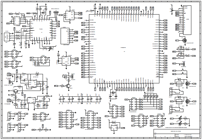
DefendLineII Schematics
Previous article: DefendLineII. Overview;
Next article: DefendLineII. Soldering tips;
Additional info: DefendLineII Kit;
Note: Circuit diagrams are licensed under a Creative Commons Attribution Share-Alike license, which allows for both personal and commercial derivative works, as long as they credit ‘AVR Magictale Projects’ and release their designs under the same license.


Dear Team,
I have some doubt about the backup power supply.
I wanted to feed the ~4.5 V @1.8 A to INTERN. BAT. CONN will it be OK ? Then next question during backup how will work 12V related subsystem Relay, Alarm Out etc.
If I need to add GSM module, then how I manage the current that it need.
Regards,
Pravas R Mohanty
Hi Pravas,
Sorry for such a long delay. You are absolutely right, the backup power supply is not able to power peripherals and the reason is simple – the board needs different voltages and current consumption might be quite substantial which is not an option for battery power source. The original idea was to provide the microprocessor module and some vital peripherals such as microSD card, thermometer and realtime clock with uninterrupted power sacrificing ability to control external devices (relays won’t work) and sacrificing ability to communicate with the outer world (GSM module won’t work as well). Relays need 12 volts but more important they consume current of 30 mA each so 2×30=60 mA drawing from backup power source by relays only would be a total waste. As for the GSM module, it may draw up to 2A during wireless communications and normally needs 3.7 volts, at 3.3 it shuts down. So, basically speaking, there is no voltage required voltage for GSM module when primary power is absent. At design time a decision was made not to use Lithium batteries as they don’t work in subzero temperatures and below. All in all, current configuration allows to handle alarm events during power outages, store them in AVR memory or on microSD card and send them later, when the main power is restored and GSM module is functional.
Regards,
Dmitry