


We are continuing our experiments with an alternative VFD power supply which we started some time ago. The high voltage part remains pretty much unchanged for now – it is an inverting regulator based on inexpensive chip MC34063. Excessive current consumption (60-70mA) in idling mode is still an issue but we are not going to address it today and the circuit diagram of HV part is in essence what we had during the previous experiment:
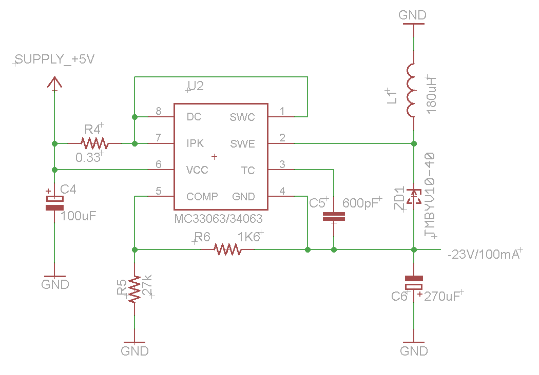
MC3463 Inverting Regulator
The second part, a filament driver, is based on a… LM4871 audio amplifier. We have been inspired by the idea described in great detail in The VFD Stuff article but what we didn’t like in the original design was a requirement for 12VDC (and we wanted a solution capable of working off 5VDC). Also, LM1877 is an old chip, so old that it doesn’t have a shutdown pin. Learnt on our previous mistakes we didn’t want to use something which could become obsolete at any point in time. Having a few things in question and before rushing and finalising our PSU design we also wanted to build a prototype to make sure that it would going to fly. So the following simplified circuit diagram was used to test its pros and cons:
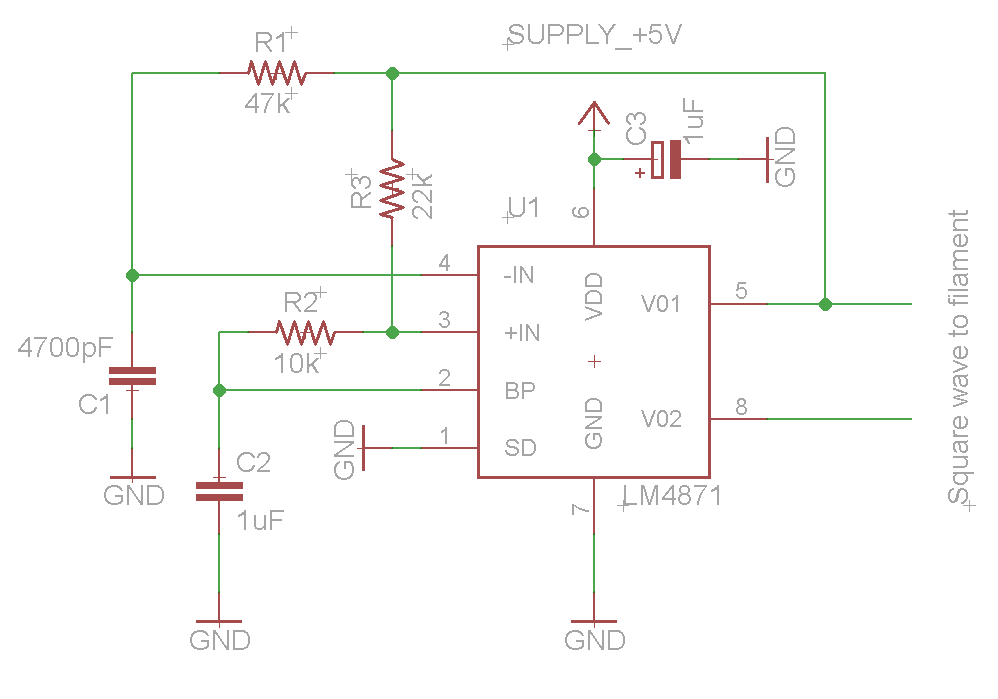
LM4871 Square Wave Generator
A SOIC-to-DIP 8 pin adapter, bunch of wires and jelly beans have been used for a proof of concept, no PCB. To our surprise, the circuit was not demonstrating stable results, the generated square wave had some parasitic spikes the amount and magnitude of which varied greatly over time and we couldn’t understand the reason.
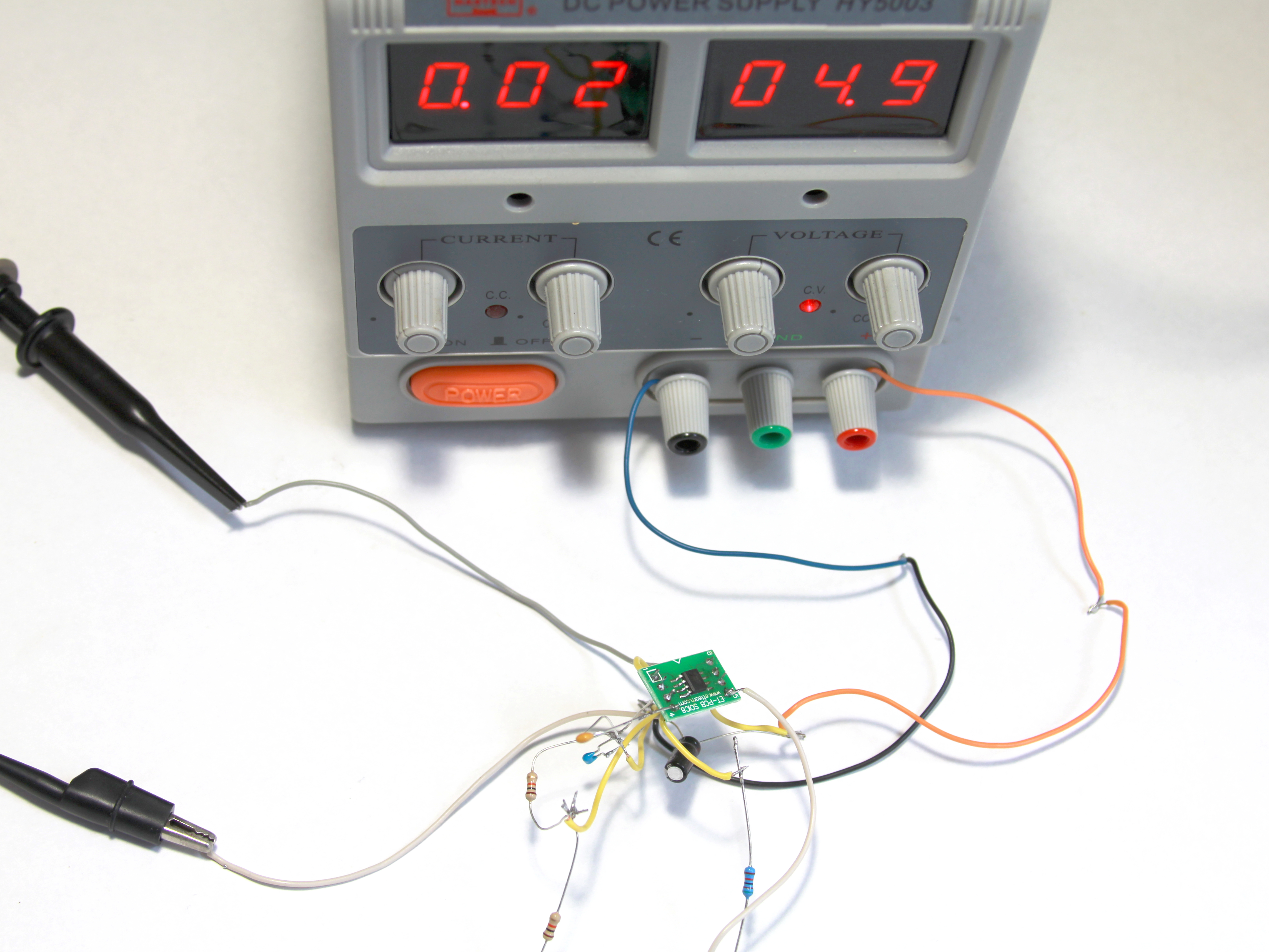
VFD_PSU_EXP01 Test Without PCB
The two pictures below shows two spikes at the beginning of a square pulse and this not a bad case as we witnessed much, much worse. Eventually, after numerous on/off switch cycles and attempts to comprehend the nature of the noise we ended up with entangled wires killing the amplifier in the end as a result.
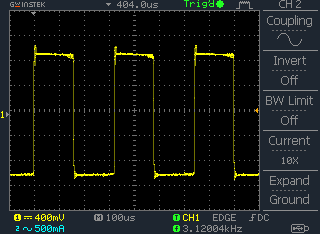
Square Wave Parasitic Spikes without PCB
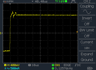
Square Wave Parasitic Spikes without PCB
After the failure we decided not to repeat same mistakes and build a prototype on a proper PCB thanks to ITead Studio, it is very cheap now. The two parts (HV and filament driver) have been merged into a single circuit diagram as shown below. We deliberately made some room for more things to try and adjust: voltage dumping resistors R7, R8 (which needs to be later replaced with something more elegant), transistor Q1 to play with current consumption in idling mode for HV part and the trick of offsetting filament AC voltage down to -20…-24V (R8, R10, C7, C8).
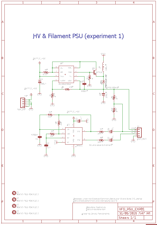
VFD_PSU_EXP01 Circuit Diagram
The board was easily routed and fitted on a standard blank of 50x50mm, some real estate has been even reserved for prototyping area. All components reside on a top layer as shown below:
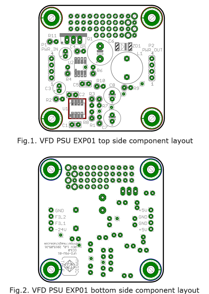
VFD_PSU_EXP01 Compoment Layout
Then a 3D model of PCBA was designed to make sure that there was no interferences between components and nothing was overlooked:
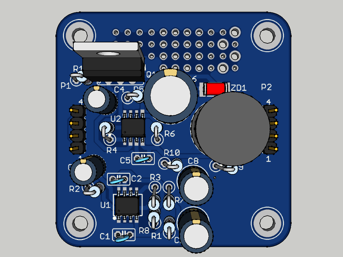
VFD_PSU_EXP01 PCBA 3DModel Top View
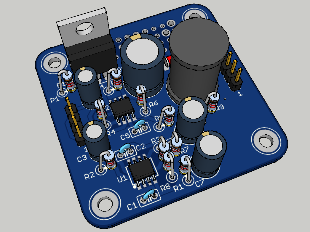
VFD_PSU_EXP01 PCBA 3DModel Top ISO View
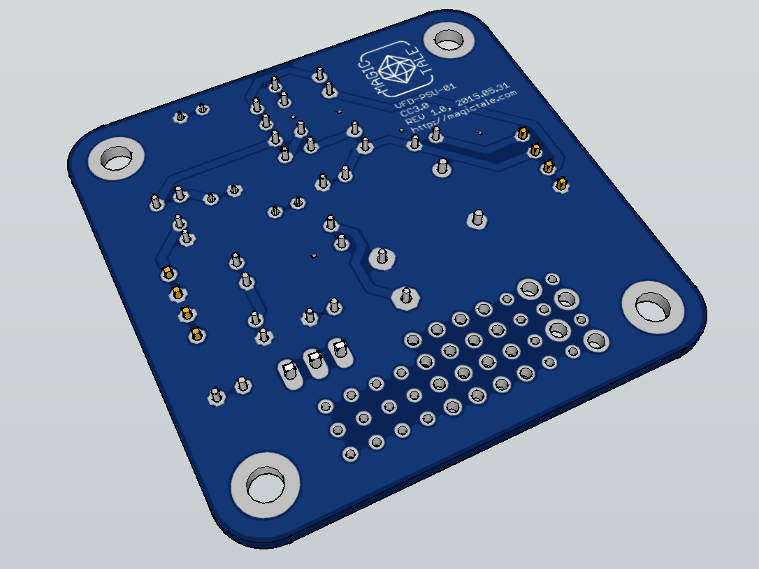
VFD_PSU_EXP01 PCBA 3DModel Bottom ISO View
The manufactured PCBs arrived exactly in two weeks, no surprises here:

VFD_PSU_EXP01 PCBs Manufactured
First PCBA has been loaded with components, as per original schematics Q1 and R11 are not loaded instead Q1 Base and Emitter are connected with a wire, R10 is not loaded and R10 is replaced with a wire.
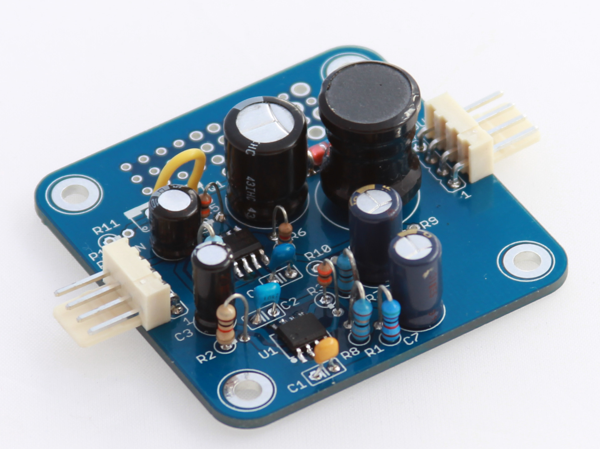
VFD_PSU_EXP01 PCBA Assembled
Generated square wave is much more cleaner now, all parasitic spikes disappeared:

Square Wave No Parasitic Spike On PCB
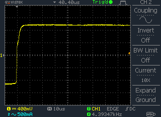
Square Wave No Parasitic Spike On PCB
And the most important step is actual connection of a VFD. As we don’t have any controller at the moment we can simply apply filament voltage and pull one grid and one segment to ground (not to -24V, it is actually filament voltage which oscillates about -24V). The picture below shows that our prototype works even though is consumes a bit excessive current – 230 mA. Our goal would be to bring it down to 150 mA in the next exercise.
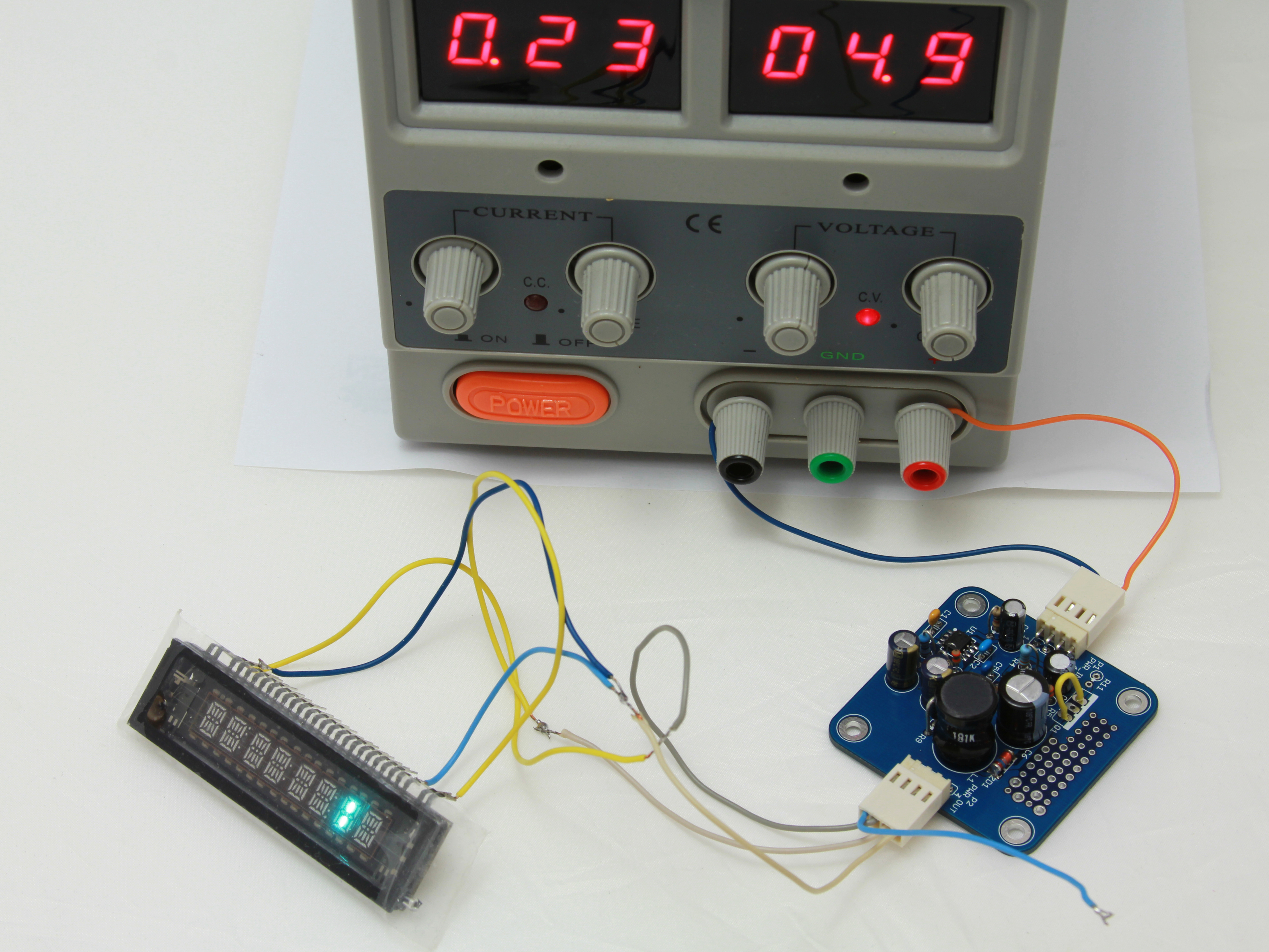
VFD_PSU_EXP01 In Action
Downloads:
1. VFD_PSU_EXP01 Gerber files Rev1.0
2. VFD_PSU_EXP01 Eagle files Rev1.0
3. VFD_PSU_EXP01 PCBA SketchUp 3D Model Rev1.0


Leave a Reply
You must be logged in to post a comment.