


First Pilot Display PCB is finally assembled and tested. As it usually happens with revisions 1.0 there are several things that have been overlooked during design. Good news is that all issues are minor and don’t impact main functionality. Here are the discovered issues:
a) First of all, FT232 is not powered when USB cable is not connected resulting TXLED and RXLED outputs being pulled low and as a consequence LD1 and LD2 are constantly switched on. Connecting USB cable puts both LEDs to the desired (switched off) states even when the cable is then unplugged. This is annoying but given that both LEDs are powered with 1K resistors in series, it doesn’t make much of a difference in power consumption even with both LEDs being permanently switched on.
b) The next problem though is ST3232BSOIC16 which shares RX-I and TX-O signals with FT232. ST3232BSOIC16 never puts its outputs into hi-z state and therefore microprocessor ATMEGA1284PA can’t receive data from FT232 which is essence means that USB interface cannot be used for firmware updates, maximum that we can get is a debug output through USB. However, firmware updates still can be done via RS232 interface for the left engine (TX_LEFT and RX_LEFT). In the next revision it will be worth adding a jumper to manually switch between serial and USB interfaces;
c) R5 resistor doesn’t make much sense and better to be replaced with 0.1uF ceramic capacitor;
d) Both MAX6957 are not designed to put their DOUT outputs into hi-z mode when not selected by SS which creates conflicts on the SPI bus when the microprocessor is being programmed via ISP header. We managed to program the microprocessor by cranking up VCC to 5V via ISP header. Once the bootloader is programmed, there is no need in ISP anymore as from that point the firmware can be updated via RS232 interface without need to use external ISP programmer;
e) Really strange and unexpected issue – red LEDs are slightly bigger than green and orange ones despite they all are of the same form factor. Attempts to find another type of red LEDs resulted in the same slightly bigger sizes!
f) LEDs are really difficult to solder precisely so it would be worth using LED spacers for the next boards;
g) At the end of this design cycle the customer expressed a desire to have opto-isolation for both RS232 ports so looks like that ST3232BSOIC16 would need to be replaced with something else;
The DC-DC converter is capable of delivery up to 1A @ 3V3 and was successfully tested under maximum load by switching all LEDs simultaneously at maximum current of 20mA per LED. No excessive power dissipation is under maximum load – all chips remain cold when touching with a finger.
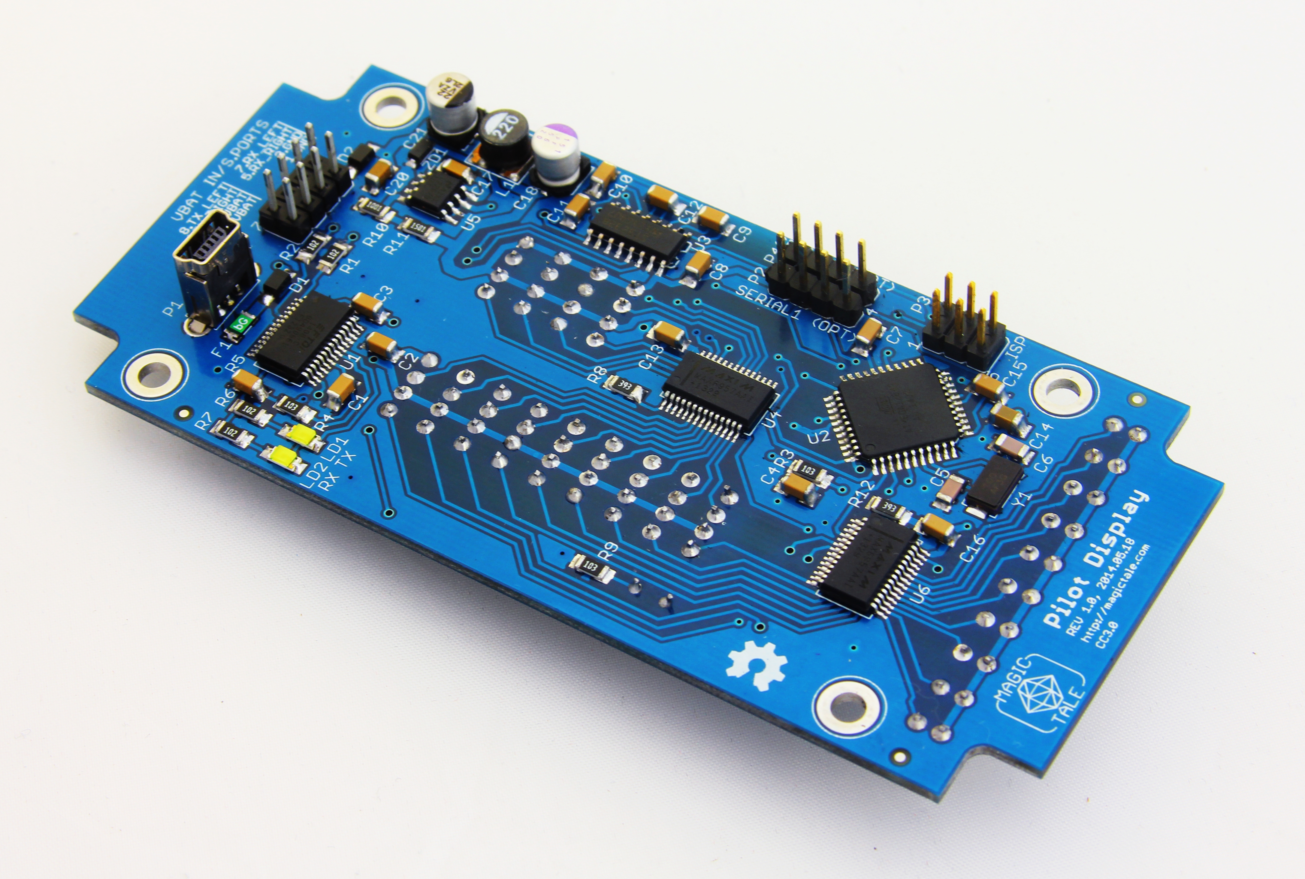
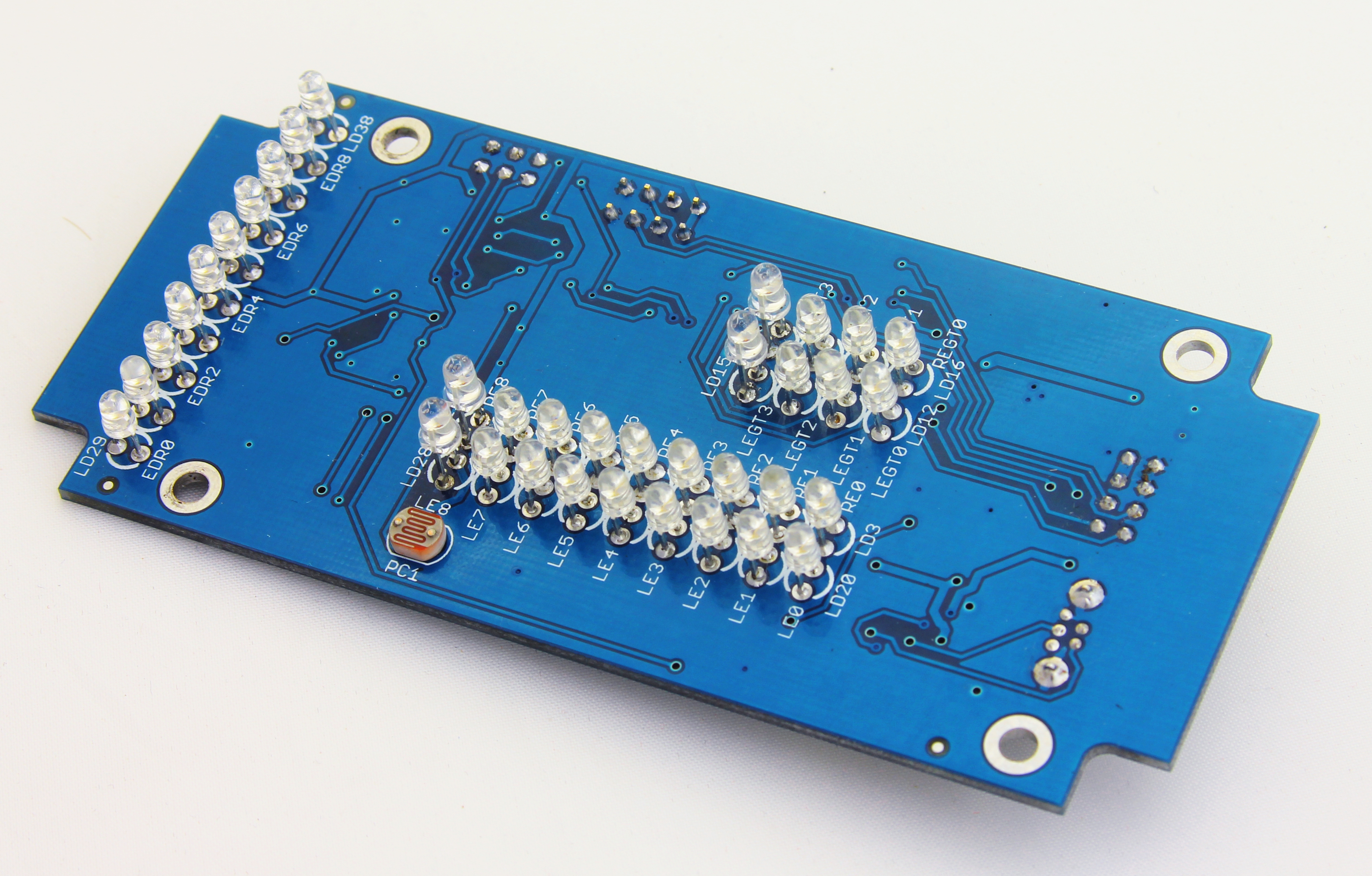
Fully assembled board is shown on the pictures below.
Pilot Display PCBA Bottom
Pilot Display PCBA Top


Leave a Reply
You must be logged in to post a comment.