A bootloader is a compact executable code often flashed in upper program memory area implementing basic transfer protocol and facilitating self-programming function, making possible firmware updates without need to have an external programmer. In most cases bootloaders simulate basic programmers to take advantage of already existing software support without invention of something new. Of course, initially a bootloader must be flashed by means of an external programmer.
To begin with, DefendLineII PCB must have as minimum the following components soldered: U3, C30, C31, Y3 (CPU and clock source); CONN20 (ISP connector for serial programming), R33, R34, LED2, LED3 (LEDs to indicate device states); L1, C4, C5.
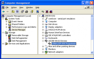
Next we need an ISP programmer, let’s take as an example USBtinyISP AVR ISP Atmel Programmer. It costs only US $15.50, supplied with two flat cables (for 10 and 6 pin connectors) and is capable of providing a flashing board with +5V that is why there is no even need to solder power supply components at this stage. Download USB drivers required for the programmer, they are available here. Connect the programmer to a PC over a USB cable, Windows should report about newly found device and will ask for drivers. Unzip and install just downloaded archive. Now in Device Manager a new device called USBtinyISP AVR Programmer should appear in LibUSB-Win32 Devices group. The ISP programmer is ready for work, see the screenshot below:
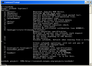
Now we need WinAVR, open source software development tools for the Atmel AVR microprocessors. The project contains many tools and utilities, development libraries, plenty of examples, tons of documentation and, of course, source codes but right now we will be using avr-gcc (C/C++ compiler) and avrdude (software support for huge diversity of AVR ISP programmers). Download the latest version and install the project. Open Command Prompt and type ‘avrdude’. If everything has been done correctly, a list of avrdude options will be displayed:
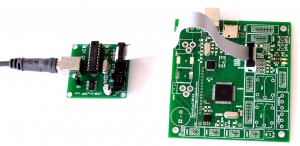
Now it is time to test whether the programmer can communicate with PC and the board. Connect the board and the programmer with 10-wire flat cable but before make sure that programmer’s ‘PWR’ jumper is closed – in this case the board won’t need a power supply (at least for now):
Type in Command Prompt the following command:
avrdude -p m1280 -c usbtiny -U hfuse:r:high.txt:h -U lfuse:r:low.txt:h -U efuse:r:ext.txt:h
If the board is functional the programmer will read high, low and extended values of fuse bites and write them in high.txt, low.txt and ext.txt files accordingly. Check the values of fuse bits carefully. In order to support external crystal and bootloader the following values must be written to the chip: 0x98 for high fuse byte, 0xD7 for low and 0xFF for extended one. If you have different values they can be changed with the following commands:
avrdude -p m1280 -c usbtiny -U hfuse:w:0x98:m
avrdude -p m1280 -c usbtiny -U lfuse:w:0xD7:m
avrdude -p m1280 -c usbtiny -U efuse:w:0xFF:m
Download source code for DefendLineII project. It might be done in two ways. If you have SVN tool installed then the following line in Command Prompt will create project’s folders along with all project’s files:
svn co https://defendline2.svn.sourceforge.net/svnroot/defendline2 defendline2
The target files will be located in \defendline2\CPP\BootLoader\ folder.
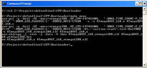
In case if you don’t have SVN installed you can simply download the files by browsing DefendLineII Bootloader in SVN repository. An already compiled file for flashing called ATmegaBOOT_168_atmega1280.hex could be fed to ISP programmer directly but in case if you want to compile it yourself you will need ATmegaBOOT_168.c and Makefile. Change the current directory to the one where these files are located and type the following command:
make mega
In case of success you should see something like this:
A just compiled ATmegaBOOT_168_atmega1280.hex will be located in the same directory. Now it could be flashed to the board, type the following line in Command Prompt:
avrdude -p m1280 -c usbtiny -U flash:w:ATmegaBOOT_168_atmega1280.hex
This procedure takes a few minutes because avrdude will flash almost all program memory despite that fact that the bootloader occupies only upper 4 kBytes. When the flashing is completed a control will be given to bootloader section first, the bootloader will start and attempt to read a command from PC host. Before that an onboard orange LED will blink, it is a good indication that everything is just fine.
Next step is to solder USB and power supply related components: U4, LED1, JP1, R3, R5…R10, C1, C2, C3, C6, C7, CONN1, Y1 (USB port hardware support); SB1 (for forcing device to start bootloader when flashed); CONN9, L3, L4, D4, D5, C32-C35, U7, R25, R26 (main power supply). When it is done, power up the board over CONN9 connector, there should be about +12V. Check the voltage after U7 DC-DC converter, it should be about +3.3V.
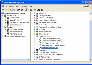
Disconnect USBtiny AVR programmer and connect the board to PC via USB, Windows should report about newly found virtual COM port and will install the drivers automatically. Now in Device Manager a new device called USB Serial Port should appear in Ports(COM&LPT) group, see the screenshot below:
As avrdude has a limitation in serial ports range (from COM1 to COM4 only), we need to allocate the virtual serial port to COM3 or COM4 (COM1-COM2 are usually taken). Don’t forget to set port speed to 57600 in port’s settings.
Now you are able to update board firmware without any external ISP programmer, for instance, to flash DefendLineII.hex you need to issue the following command:
avrdude -p m1280 -c avrisp -P com4 -b 57600 -U flash:w:DefendLineII.hex
Note, that this time we use ‘avrisp’ programmer type and explicitly defining COM port and baud rate. There is also a trick: at first the abovementioned command should be issued then the DefendLineII board should be reset or powered up because the bootloader waits for some short period of time for a command from PC host and then it gives a control to the main program located at 0x0000 address in program memory. Another way to initiate flashing process is to hold SB1 button while the board is being powered up and until the flashing process starts.
Previous article: DefendLineII. Soldering tips;
Next article: DefendLineII. Building Firmware;
Additional info: DefendLineII Kit;



Leave a Reply
You must be logged in to post a comment.