Now when we have full control over VFD display, it is time to build something meaningful. How about remotely controlled clock with temperature sensor? Boring? Well, it will be unusual device: capable of working from virtually ANY type of remote control, with display activated by a motion sensor, with capability to log current temperature to an external USB host (i.e. PC, laptop or Android phone) and in custom made acrylic enclosure!
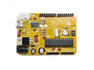
As a heart of the system Freeduino board would be probably an ideal choice: more than enough computational power, abundance of GPIOs, the amount of program memory is roughly just right for this type of project, compact dimensions (we really need it because the VFD panel and the power supply are rather bulky so we would aim to achieve to minimum possible size for our box). And finally, this board is really cheap.
The board comes as a kit so it is a good chance to practice in soldering yet all components are very easy to solder.
As an advantage, the board does not need any external programming equipment – it has serial-to-USB converter and could be connected directly to a PC and programmed by means of Arduino IDE. In fact, it is possible to program it even without Arduino IDE as such – everything that needs to be installed is AVRdude.
After programming procedure serial port might be user for debugging output or, in our case, for logging current temperature to external device.
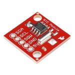
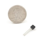
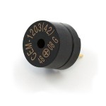
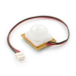
Also we would need extra components, such as real time clock module, temperature sensor, PIR sensor and a basic speaker or buzzer, all of them are available at Sparkfun Electronics. Real time clock module would keep accurate track of the current time with a calendar up to year 2100, capable of surviving power outages and requiring just two signal wires for communication with main processor. Digital temperature sensor with 12-bit precision would require even less – just one signal line to control it. The job of PIR passive motion sensor would be to activate display when motion is detected so that after a predefined timeout the display goes to standby mode saving energy and VFD resource and making the device more interactive. The purpose of buzzer is to demonstrate that the microcontroller still has some computational power to generate primitive sound so the clock might be easily converted into alarm clock.
We also would need a remote control to manipulate clock settings and the type of RC (whether it is NEC, SONY, RC5 or RC6 standard) really does not make any difference simply because we are going to support… all types! To say more, the initial set up of a remote control for use with our clock will be done by means of… a remote control! How? Read on and it will be explained for you later.
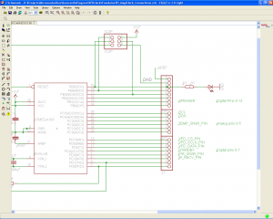
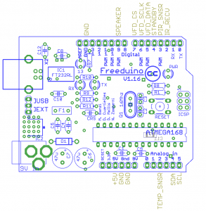
Time to connect modules together. Two pictures below show pinouts for signal and power lines on our Freeduino board.
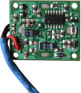
There are couple of tricks again. Firstly, the PIR sensor works stable from +12V and allows false alarms when the voltage is +5V (which is exactly our case). This is because it has voltage regulator 7805 and +5V is not enough for proper regulation. Bypassing the regulator (connecting +5V to its output leaving input unconnected) solves the issue.
Secondly, the standby mode on VFD panel is controlled by a chip IC581 that flips the state of its PCON output when it detects a pulse on its POWER input. It has been discovered that sometimes it may detect a false pulse induced by appliances located nearby. Besides, there is no way for our Freeduino to detect which mode (ON or STANDBY) is currently active. The solution is very simple – to unload R582 and therefore disconnect IC581 from controlling the standby line and instead connect Q581 via 1K resistor to our Freeduino board. So the ON/STANDBY mode will be controlled not by pulses but by levels.
Here is the signal mapping table between Freeduino board and the remaining components (please also refer to DVP630 Schematic Diagram):
| Signal | Freduino connector-pin | Component-Connector-pin |
|---|---|---|
| VFD_CS | J3-8 | VFD panel-RB502-2 |
| VFD_CLK | J3-7 | VFD panel-RB502-1 |
| VFD_DATA | J3-6 | VFD panel-RB502-3 |
| STANDBY | J3-5 | VFD panel-Q581-base, via 1kOhm; R582 must be unloaded |
| IR_RECV | J3-3 | VFD panel-RB502-5 |
| +5V Standby | JP1-3 | VFD panel-RB501-5, RTC Module-5V Pin, DS18B20-VCC Pin, PIR Sensor-in bypass of voltage reg. |
| GND | JP1-4, 5 | VFD panel-RB502-4, Buzzer-‘-‘ Pin, RTC Module-GND Pin, DS18B20-GND Pin |
| SPEAKER | J1-2 | Buzzer-‘+’ Pin |
| PIR_SNSR | J3-4 | PIR Motion Sensor-ALARM (AL) Pin |
| TEMP_SNSR | J2-3 | DS18B20-Data pin |
| SCL | J2-6 | RTC Module-SCL pin |
| SDA | J2-5 | RTC Module-SDA pin |
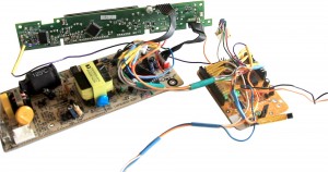
Fully assembled electronics is shown on the picture below (though the connector to RTC module is temporary disconnected and PIR sensor is not shown yet wires on the bottom on the picture lead to it).
Electronics is ready but firmware is not programmed yet. Next step briefly tells how to do it. Download the firmware (following the link at the end of this post). To program the firmware connect Freduino board to PC using USB cable wait until a new virtual port is installed then just type the following in Windows Command Prompt (but before make sure that AVRdude is installed on your PC):
avrdude -p m328p -c avrisp -v -P comXX -b 57600 -U flash:w:VFD_MagiClock_Rev1.0_2012_09.29.hex
where comXX is your newly installed COM port name (i.e. COM10, COM15).
When the programming procedure is completed, our application starts and Freeduino activates VFD display straight away displaying greeting information and then awaiting for RC setup. If within a few seconds no commands from RC have been received, the device goes to its normal mode displaying periodically time, date, day of week and temperature.




Leave a Reply
You must be logged in to post a comment.