


Some time ago we began looking for alternative displays for our Luminardo project and got inspired by a DIY OLED interface board. The author found cheap monochrome OLED displays on Ebay, designed an interface board and wrote a C library. In addition to that some more information on driving such display type was found at DGK Electronics. The displays looked bright and thin, the board was compact and simple, the display was controlled via standard either I2C or SPI interface so we decided to give it a try. After doing a bit of search it was discovered that there were big variety of such displays including some which were already fitted on small PCBs yet the price tag was still below $10. Finally we ended up ordering couple of 128×32 displays without PCB and one 128×64 mounted on a PCB and controlled via I2C. When they eventually arrived, we realised that we actually misjudged their size – in fact they were really small, much smaller than our Luminardo so there was probably no point in designing yet another ‘Luminardo display shield’. Nevertheless, let’s get started our experiments.
First of all, we need physically connect OLED display and Luminardo board. Luminardo conveniently has a designated connector for interfacing with I2C devices, it is P4. The wiring between two boards is given in the table below:
| Net name | Luminardo P4 con. pin num | OLED pin name |
|---|---|---|
| +3.3V | 1 | VCC |
| SDA | 2 | SDA |
| SCL | 3 | SCL |
| GND | 4 | GND |
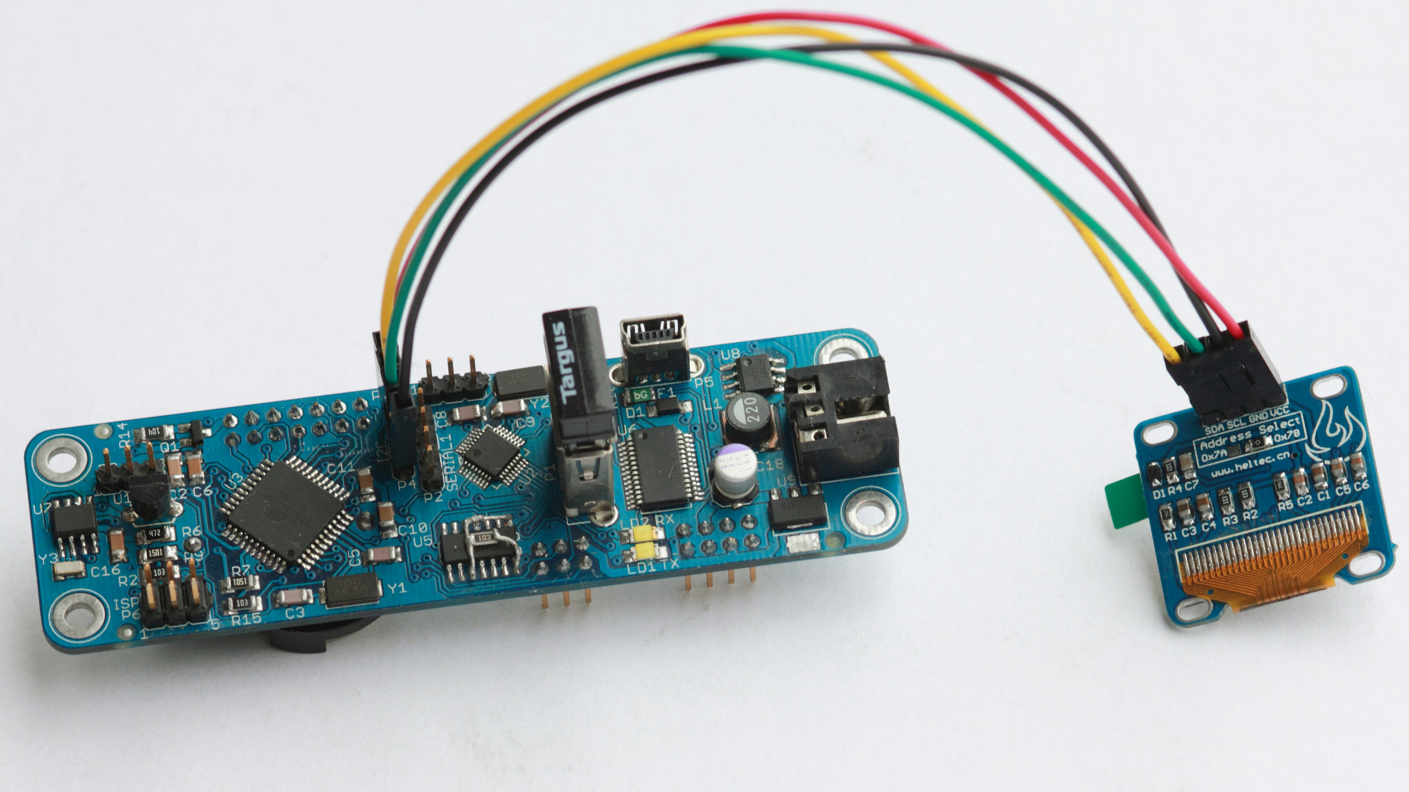
Wiring Luminardo and SSD1306 OLED Display via I2C
Now we need a library to control the display. There are plenty of different flavors out there but the most comprehensive and well known is the one designed by Adafruit company which is called Adafruit_SSD1306. Well, at least the library seemed the best to us before we began using it, what is wrong with it you we learn pretty soon in this article.
The installation of the library is described in great detail at Adafruit SSD1306 Tutorial. As we are experimenting with I2C version of 128×64 pixels display we will need to run SSD1306_128x64_i2c Arduino sketch. Compile it for Luminardo platform and try to run. If the display doesn’t work, try to initialise I2C interface with 0x3C instead of 0x3D, it worked for us:
display.begin(SSD1306_SWITCHCAPVCC, 0x3C); // used to be 0x3D
Also, note that our display doesn’t have reset pin so we defined a dummy GPIO:
#define OLED_RESET 0
Adafruit_SSD1306 display(OLED_RESET);
Once the display becomes alive and Luminardo happily runs Adafruit demo it is time to create our own picture. Let’s say, we want to design a ‘Magictale’ logo. First, find or draw a picture of icosahedron as the example below:

An Icosahedron
The picture is then resized and cropped to fit 128×64 pixels using GIMP and then converted to monochrome using ImageMagick with the following command:
convert icosa.gif -monochrome monochrome_icosa.gif
… and resulting in the following picture:

Icosahedron Monochrome
Next step then is to convert monochrome picture into C byte array with help of Picture To C Hex Online converter:

Picture To Byte Array Online Converter
We almost ready to send our picture to the display. However, there is one inconvenient moment: Adafruit’s library has a method drawBitmap(int16_t x, int16_t y, const uint8_t *bitmap, int16_t w, int16_t h, uint16_t color) which expects a pointer to a picture byte array and picture width, height being specified separately. It makes things look ugly as those values must be in essence hardcoded every time when we want to draw a picture. Why not to make ‘width’ and ‘height’ part of picture’s byte array? If so, each byte array, apart from picture itself, would have a two byte descriptor which specifies picture format:
static const unsigned char PROGMEM
Clock[] =
{
62, 63, //62x63 pixels
0x00,0x00,0x01,0xff,0xfc,0x00,0x00,0x03
...
,0x00,0x00,0x00,0x0f,0xc0,0x00,0x00,0x03
};
And the generic function-wrapper around drawBitmap will be defined as follows (it also automatically applies adjustment to the screen center):
void drawBitmapCentred(const uint8_t *bitmap, uint16_t color)
{
uint8_t b_width = pgm_read_byte(bitmap++);
uint8_t b_height = pgm_read_byte(bitmap++);
display.drawBitmap((display.width() - b_width) / 2, (display.height() - b_height) / 2, bitmap, b_width, b_height, color);
}
Next step would be to replace standard Adafruit splashscreen with something else. You won’t find splashscreen bitmap explicitly defined anywhere. The trick is in framebuffer which is defined as static uint8_t buffer[SSD1306_LCDHEIGHT * SSD1306_LCDWIDTH / 8] in Adafruit_SSD1306.cpp. The framebuffer is used to keep ‘a snapshot’ of the display content, it is physically located in ATMega’s RAM. So upon application boot the content of the framebuffer is filled with default values which represent Adafruit logo. Obviously, it could be changed if you are annoyed to see Adafruit logo every time when you switch your device on.
The pixels in framebuffer don’t go in the same order as we have it in our bitmaps – from left to right and from top to bottom, so we can’t just replace the content of the buffer with our new picture as it will result in chaotically scattered pixels. But the good thing is that we don’t need to know the format of the framebuffer – all we need to do is to draw a new logo using drawBitmap, drawChar or by drawing any of geometrical primitives and then dump the content of the whole framebuffer as byte array via Serial port. So Adafruit_SSD1306 will need the following method to be defined:
void Adafruit_SSD1306::bufToSerial()
{
for (uint16_t i = 0; i < SSD1306_LCDHEIGHT * SSD1306_LCDWIDTH / 8; i++)
{
Serial.print("0x");
Serial.print(buffer[i], HEX);
Serial.print(", ");
}
}
Now, when we get framebuffer dump, we just copy-and-paste it to static uint8_t buffer in Adafruit_SSD1306.cpp. This is what we got as a logo in our case:
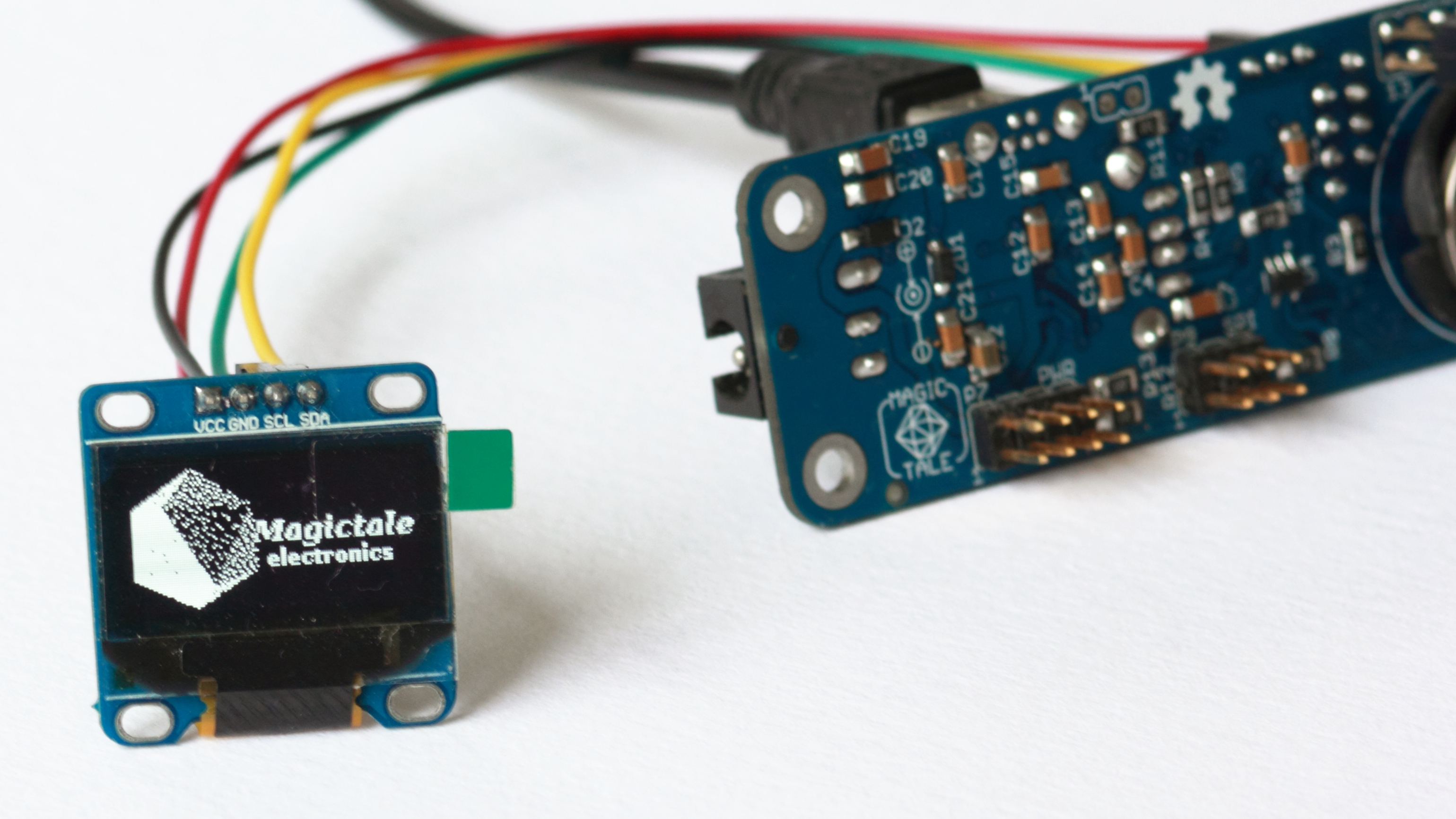
Luminardo and SSD1306 OLED Display Custom Splashscreen
Now we came to a point when it would be extremely useful to define more than one font. The standard one embedded into the library is only 5×7 pixels and while there is a functionality to specify font size everything bigger than size one looks really ugly. It would be very handy to have more than just one font at our disposal, for example, a higher definition font which simulates seven segment digits. We are not going to draw new font and just try to reuse the one from UTFT library defined as 2Kb SevenSegNumFont in DefaultFonts.c. The font already has 4 byte descriptor specifying character width and height in pixels, first character defined in font and total number of characters defined (as the is obviously no need to waste space for all 255 characters if we are going to define only 10 digits). We will also add one more byte to font descriptor which would tell a bit more how a character is defined in byte array. The newly added seven segment font will be defined as follows:
// SevenSegNumFont
// Font Size	: 32x50
// Memory usage	: 2005 bytes
// # characters	: 10
static const unsigned char sevenSegNumFont[2005] PROGMEM={
0x20,0x32,0x30,0x0A, 1 << FONT_OPT_BIT_DIR,

//the font actually starts here
0x00,0x00,0x00 ...
};
Let’s have a closer look at the fifth byte in font’s descriptor. It has two options, FONT_OPT_BIT_DIR and FONT_OPT_COLUMNS. The first option tells how character bits are defined in byte array – normally, from left to right/top to bottom or in reversed order. The second option tells whether character is specified column by column or row by row. All these options really depend on font resolution and an attempt to specify all fonts the same way would result in bigger byte arrays and therefore inefficient memory usage.
In order to support multiple fonts, Adafruit_GFX class has two more members: const uint8_t* _currfont; and uint8_t _fontPitch;, implementation of drawChar is significantly redesigned (as there were too many hardcoded things and shortcuts), write method is changed and setFont method is introduced:
#if ARDUINO >= 100
size_t Adafruit_GFX::write(uint8_t c) {
#else
void Adafruit_GFX::write(uint8_t c) {
#endif
const uint8_t* fontpntr = _currfont;
uint8_t c_width = pgm_read_byte(fontpntr++);
uint8_t c_height = pgm_read_byte(fontpntr++);

if (c_width > c_height)
{
uint8_t tmp_width = c_width;
c_width = c_height;
c_height = tmp_width;
}

if (c == '\n') {
cursor_y += textsize * c_height + _fontPitch;
cursor_x  = 0;
} else if (c == '\r') {
// skip em
} else {
drawChar(cursor_x, cursor_y, c, textcolor, textbgcolor, textsize);
cursor_x += textsize * c_width + _fontPitch;
if (wrap && (cursor_x > (_width - textsize * c_width + _fontPitch))) {
cursor_y += textsize * c_height + _fontPitch;
cursor_x = 0;
}
}
#if ARDUINO >= 100
return 1;
#endif
}

// Draw a character
void Adafruit_GFX::drawChar(int16_t x, int16_t y, unsigned char c,
uint16_t color, uint16_t bg, uint8_t size)
{
const uint8_t* fontpntr;

fontpntr = _currfont;
uint8_t c_width = pgm_read_byte(fontpntr++);
uint8_t c_height = pgm_read_byte(fontpntr++);
uint8_t start_chr = pgm_read_byte(fontpntr++);
uint8_t end_chr = start_chr + pgm_read_byte(fontpntr++);
uint8_t fnt_options = pgm_read_byte(fontpntr++);

uint8_t bt_msk = 0x1;
if ((fnt_options >> FONT_OPT_BIT_DIR) & 0x1 == 1) bt_msk = 0x80;
bool column_first = false;
if ((fnt_options >> FONT_OPT_COLUMNS) & 0x1 == 1) column_first = true;

if (c < start_chr || c >= end_chr) return;

c -= start_chr;

if((x >= _width)            || // Clip right
(y >= _height)           || // Clip bottom
((x + (c_width + 1) * size - 1) < 0) || // Clip left
((y + (c_height + 1) * size - 1) < 0))   // Clip top
return;

uint8_t line;
uint8_t x_resolution = c_width / 8;
if (c_width % 8 != 0) x_resolution++;

for (uint8_t i = 0; i < c_height; i++)
{
for (uint8_t j = 0; j < x_resolution; j++)
{
uint16_t offset = c * x_resolution * c_height + i * x_resolution + j;
line = pgm_read_byte(fontpntr + offset);

for (int8_t k = 0; k < 8; k++)
{
if (line & bt_msk)
{
if (size == 1) // default size
{
if (column_first)
drawPixel(x + i, y + j * 8 + k, color);
else
drawPixel(x + j * 8 + k, y + i, color);
}else
{  // big size
if (column_first)
fillRect(x + ((i * 8 + k) * size), y + (j * size), size, size, color);
else
fillRect(x + ((j * 8 + k) * size), y + (i * size), size, size, color);
}
}
else if (bg != color)
{
if (size == 1) // default size
{

if (column_first)
drawPixel(x + i, y + j * 8 + k, bg);
else
drawPixel(x + j * 8 + k, y + i, bg);
}else
{  // big size
if (column_first)
fillRect(x + ((i * 8 + k) * size), y + (j * size), size, size, bg);
else
fillRect(x + ((j * 8 + k) * size), y + (i * size), size, size, bg);
}
}

if (bt_msk == 1) line >>= 1;
else line <<= 1;

}
}
}
}

void Adafruit_GFX::setFont(const uint8_t* fnt, uint8_t fontPitch)
{
_currfont = fnt;
_fontPitch = fontPitch;
}
The final library support three full-blown fonts: 5×7 (smallFont), 8×12 (meduimFont) and 16×16 (bigFont). There is also a way to specify pitch – a distance in pixels between adjacent characters so in real life there is more than 3 differently looking fonts. In addition, there are 10 32×50 digits in seven segment style which make numbers much more neat:
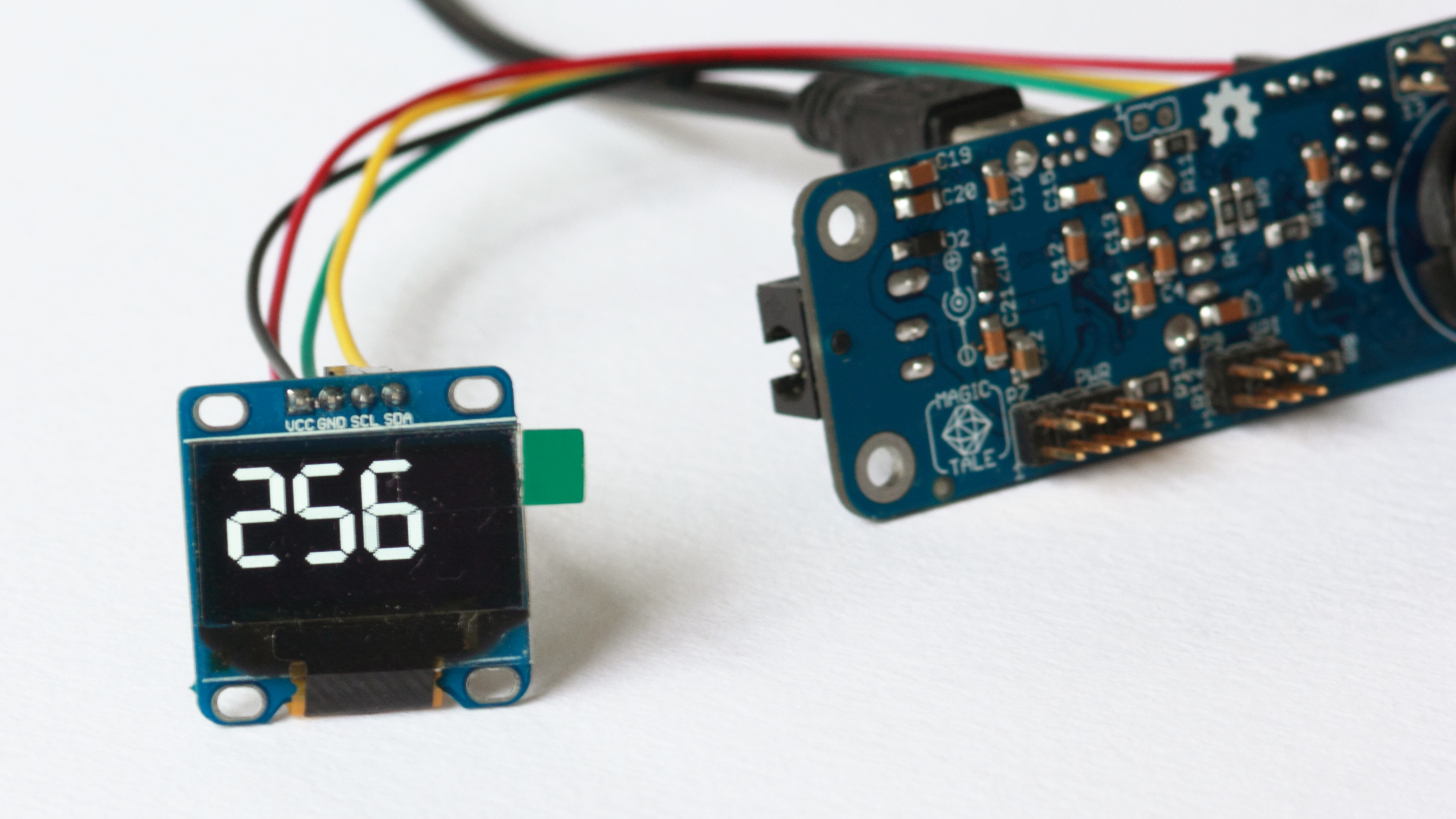
Luminardo and SSD1306 OLED Display – 7 Segment Large Digits
If you create a counter from 0 to 999 you will notice that it takes visibly longer time to render three big seven segment digits that just two or one. Given, that in order to commit changes to the display same about of data (whole frame buffer) is sent via I2C interface it means that our rendering mechanism in RAM is even slower than I2C bus (which is relatively slow thing). This is not good obviously and there should be some optimisations to the code to be done. But let’s leave it for the next exercise.
Downloads:
1. Adafruit_Luminardo_SSD1306_2015_04_06.zip – supports multiple fonts;
2. Adafruit_Luminardo_SSD1306_Blink_2015_04_08.zip – supports multiple fonts and blinking but uses 2Kb for primary and secondary frame buffers rather than just 1K for a single buffer;


Leave a Reply
You must be logged in to post a comment.