


Inspired by the success of VFD MagiClock a decision to make something similar but out of new parts was made. To be fair, despite its appealing look the original clock was assembled using scrapped parts making it really difficult to replicate. In addition to that, rather substantial dimensions and necessity to have cumbersome power supply were amongst the reasons that stimulated us to design something better. New VFD panel would need to address the following criteria:
a) Single (preferably 5V) power supply with filament and high segment/grid voltages being generated internally;
b) Dedicated VFD controller to offload main host controller from resource consuming display refreshing duties and simplify communication interface between display and main controller;
c) Low power mode when display is not used;
d) Compact dimensions;
In addition to this, it would be nice to have the following useful features:
a) Integrated photocell for brightness adjustments;
b) Integrated buzzer;
c) Integrated IR receiver for remote control;
d) Integrated RGB LED;
e) Opensource library written in embedded C++ with Arduino as a primary target platform;
f) When possible use through-hole components rather than surface mounted which would imply less demanding soldering skills if VDF panel is distributed as a kit;
g) Design circuit diagram and PCB layout in CadSoft Eagle which is extremely popular amongst hobbists and electronics engineers;
With filament and high segment/grid voltages being generated internally typical solution includes a transformer which usually a big contributor to dimensions, mass and overall costs. To overcome those obstacles a single chip VFD filament driver has been envisaged. Generated AC for filament would be used to generate high segment/grid DC by means of 5 stage voltage multiplier. A multiplier does not have costly components as it essentially comprises of diodes and capacitors. At that moment the most suitable solution looked feasible with application of LM9022 VFD filament driver. The chip had ‘shutdown’ input effectively cutting down power consumption when VFD was not used making battery power solution possibly.
A dedicated VFD controller/driver significantly simplifies communication with host controller and reduces requirements to it in terms of performance and number of available GPIOs. Display refresh occurs in a timely manner eliminating unwanted flickering and ghost effects. The VFD driver also has 8 steps dimmer circuit for brightness adjustment and high voltage outputs allowing to drive VFD segments and grids directly. A good candidate for our purposes would be HT16515 VFD driver that is widely used in DVD players.
A VFD panel with such characteristics would be extremely simple and easy for integration with embedded host controllers from electrical, mechanical and software points of view.
Integrated photocell, buzzer, RGB LED and IR receiver would enhance the range of potential applications as they usually ‘must have’ features for almost any microcontroller based DIY thing. Despite that fact that the VFD controller chip is capable of driving up to 4 LEDs we wouldn’t connect RGB LED to it, instead, its pins would be externally accessible for host controller giving the freedom of using PWM and therefore resulting in virtually endless number of colors.
As a result of designing effort the following circuit diagram for the initial revision has been created:
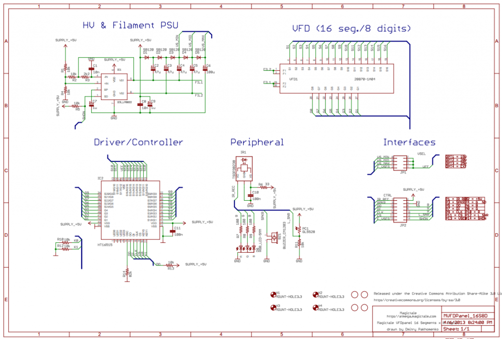
MVFD Panel 16S8D Circut Diagram Rev.1.0
The PCB layout was done on two layers with dimensions 100mm x 29mm which allows to be within limitations of ‘light’ Eagle license and take advantage of 100mm x 50mm PCB manufacturing service from ITead Studio. Component placement for top and bottom sides are given on the pictures below.
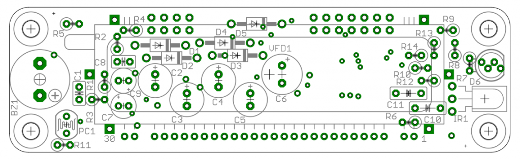
MVFDPane 16S8D PCB Rev.1.0 Comp Top
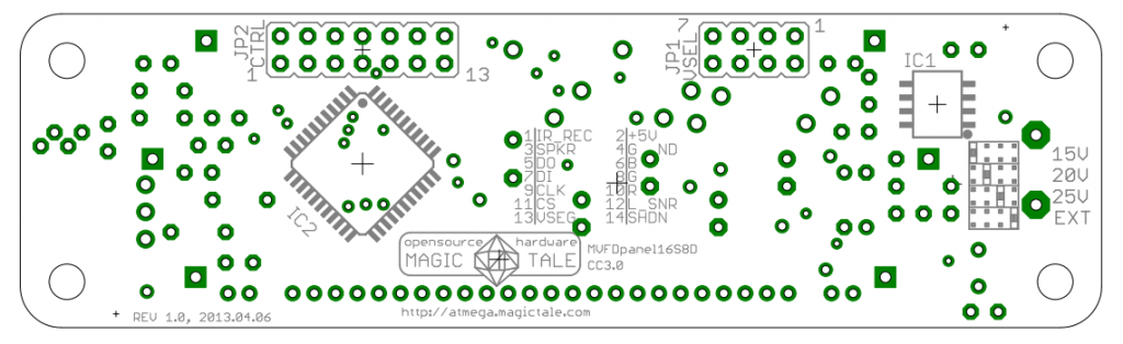
MVFD Panel 16S8D PCB Rev.1.0 Comp Bottom
Everything up to this point looked bright. Up to the moment when the newly manufactured PCBs have been finally delivered. Then we discovered that LM9022 filament driver… became obsolete a few weeks ago! The chips immediately vanished from the stocks of well-established electronic suppliers but appeared on ebay and alibaba, regrettably, with the price doubled. We didn’t have any choice so we bought the chips from ebay supplier, populated PCBs with them a few more components and hooked up a CRO. AC filament voltage was the first sign of life of the VFD panel, as it is seen on the picture below.
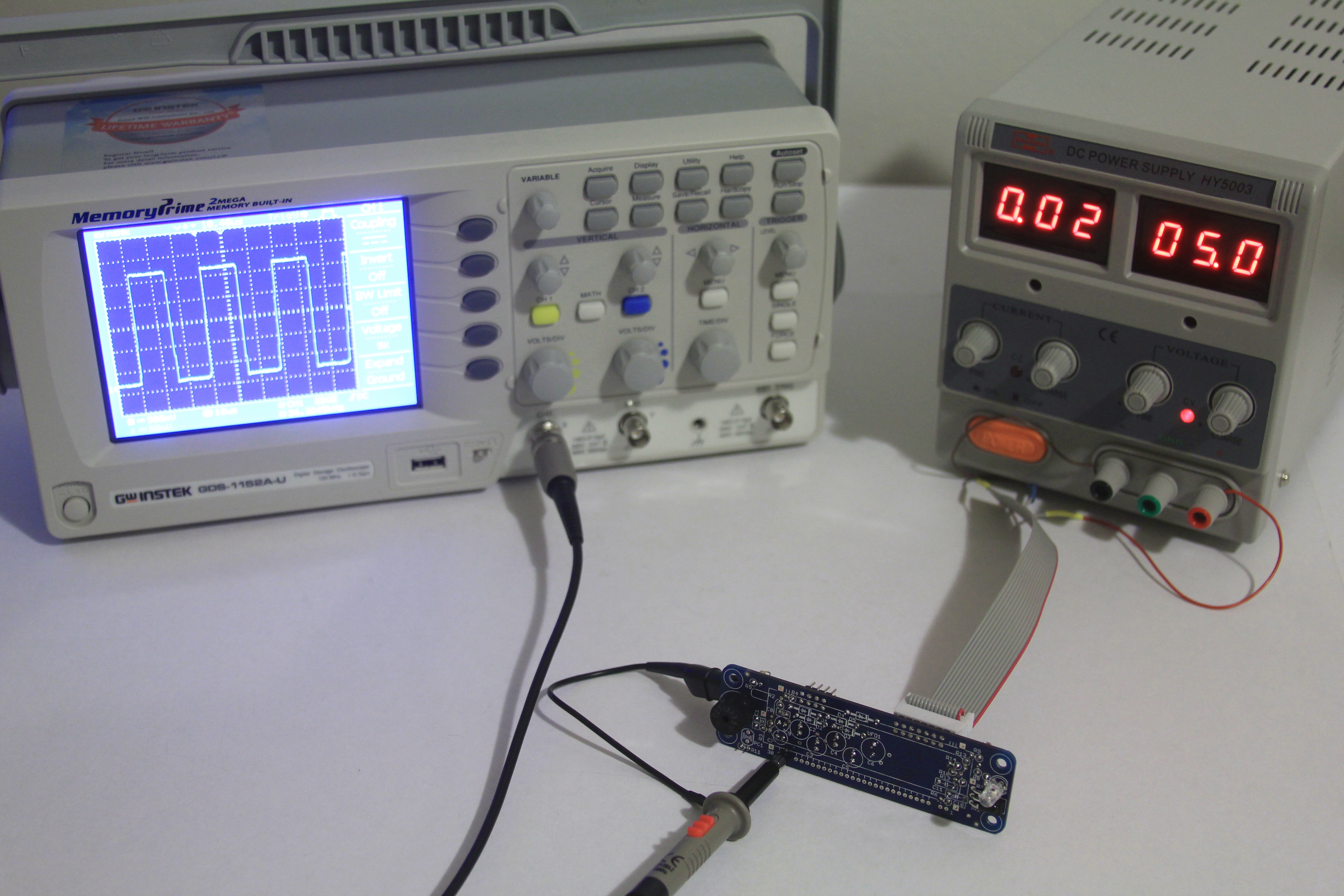
Semi-assembled MVFD Panel 16S8D CRO Hooked Up
Then there was also a problem with supply of HT16515 VFD controller – it was available in two packages, QFP and LQFP then manufacturer made QFP obsolete as well. Knowing it we designed its PCB landing pattern for LQFP package. The chips were available only at aliexpress service and ‘smart’ Chinese suppliers advertised them as ‘LQFP’ to get rid of old stocks quickly. QFP and LQFP are very similar so it was a real struggle to understand what suppliers actually had in stock. Unfortunately, QFP is slightly bigger so it is a real challenge to solder it on LQFP landing patterns. But it was just about to get even worse. First delivery of 20 HT16515 chips was literally… a scam. All chips were faulty – no even evidence of working internal oscillator when power and a couple of external components are put together. Armed with knowledge that chips in QFP packages are being sold as LQFP we tried to make it extremely clear for for the next picked Chinese supplier, he reassured us a few times that he had LQFPs, we ordered and chips arrived in QFPs again! Likely, this time chips were functional.
But it was just enough to bump into next major issue – no high voltage has been supplied to the grid and segments, even worse – after a few experiments healthy HT16515 was bricked due to unknown reason. We payed extra attention to its datasheet and to our surprise realised that the chip needed negative high voltage to drive segments, not positive and by applying any voltage higher than 0 to Vee we basically blew it up. Knowing about numerous typos in datasheets designed in Asian countries we simply overlooked that fact. After all, it didn’t look logical as everyone knows that VFD segments (anodes in fact) must have positive voltage in comparison with filament (known as cathodes). Now the whole project looked bleak as there was no place to take negative high voltage from… Or was? After many hours spent we finally figured out that yes, it would be possible to get negative high voltage if we reverse polarity of D1…D5 and C2-C6 and connect outer pin of D1 to GND instead of +5V forcing the voltage multiplier swinging in negative area. Yes, the absolute voltage wouldn’t be as high as we had originally (it was about +24V and now we can potentially get only -19V as filament AC is oscillating above zero, between 0.5V and 4.5V). But still it was a sound solution given that we had practically ruined the whole concept along with prototype.
The next problem immediately following the issue with negative voltage became filament AC voltage as now it was more positive than the negative one applied to segments/grids. Suddenly we understood the whole idea behind negative segment voltage. Surely, the VFD driver controls segments and grids by applying either zero or high negative (-24V) voltage, this probably gives some advantages when it comes to silicon chip design. But in order to make VFD display work, filament AC voltage should fall below ground as well and oscillate at around -20V or so. And to make a segment glow it would be enough to pull it to ground, to switch it off completely it should be pulled below the filament voltage so that way it will be even more negative than cathode. In reality it became apparent that there is no magic, same basic principles of VFD theory still work. To solve the issue with filament voltage we didn’t find a better way than to give up the idea of using AC generated by the filament driver and instead to scavenge it from the final stage of the voltage multiplier (between VS_MID and VS_MAX). Yes, it is not AC anymore, it is DC and there should be a resistor connected in series with VFD filament in order to dump excess of voltage a bit… ugly, but works for the first prototype at least.
As a real proof of our ideas and efforts here are the pictures of working VFD panel below:
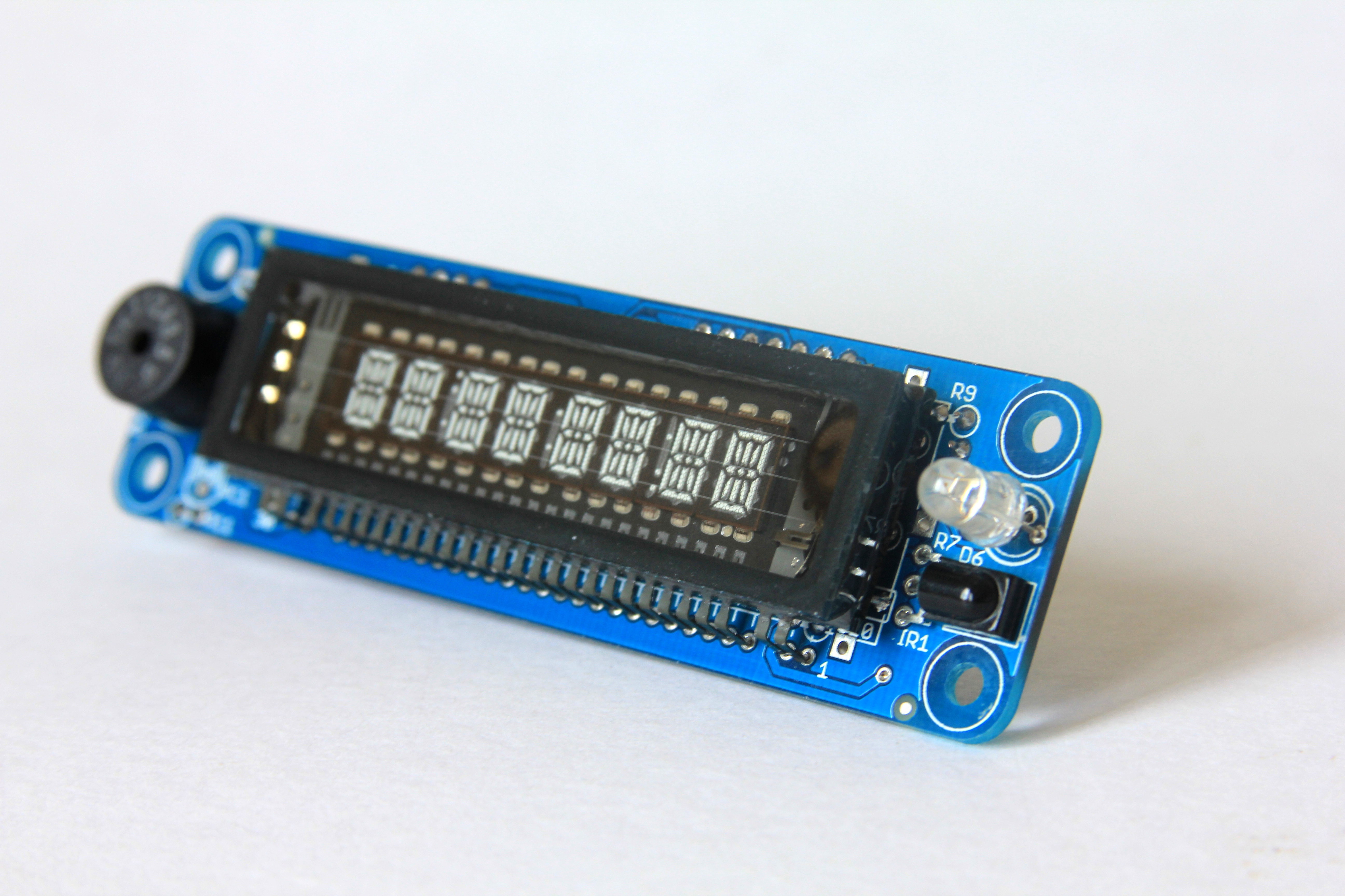
MVFD Panel 16S8D ISO View
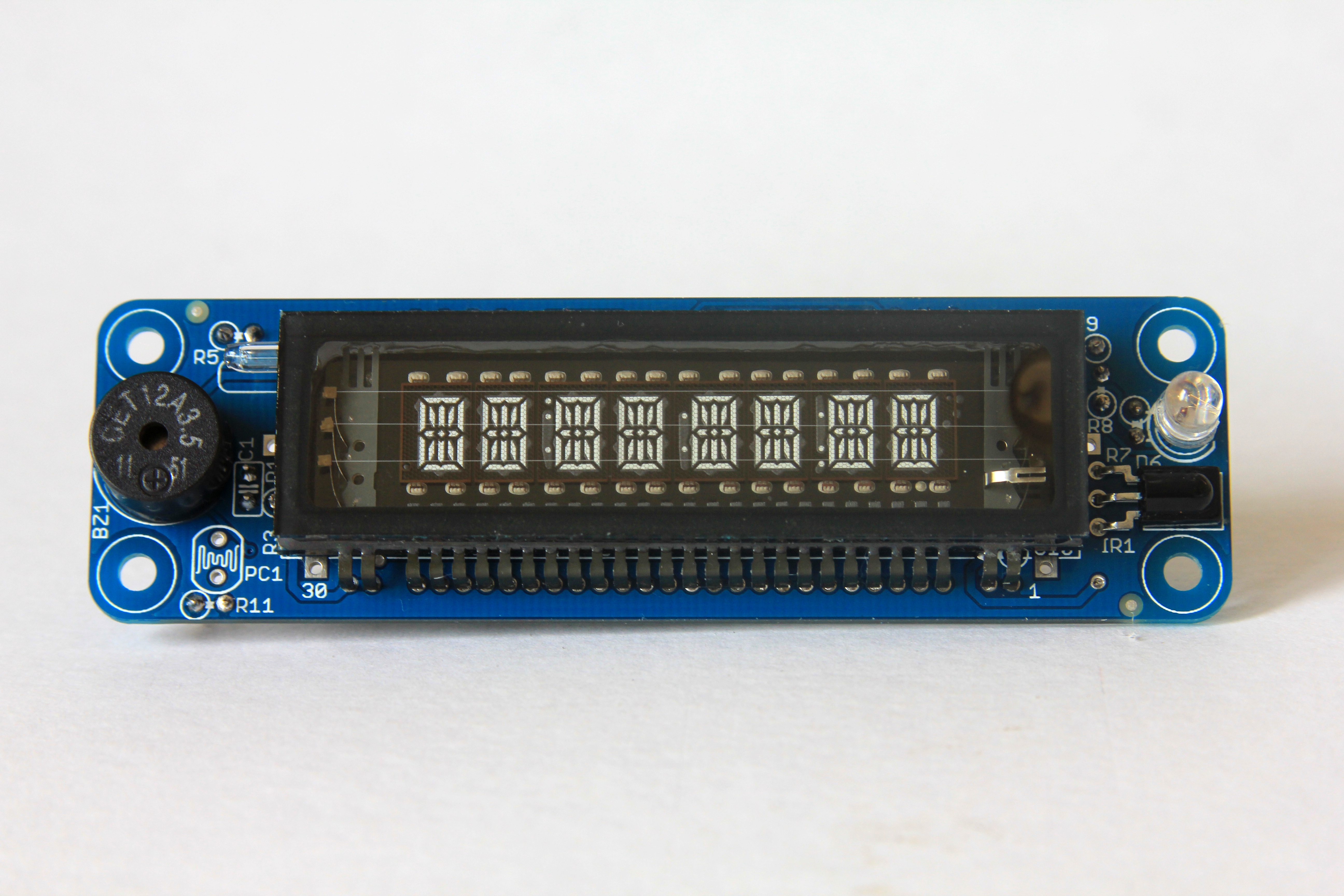
MVFD Panel 16S8D Front View
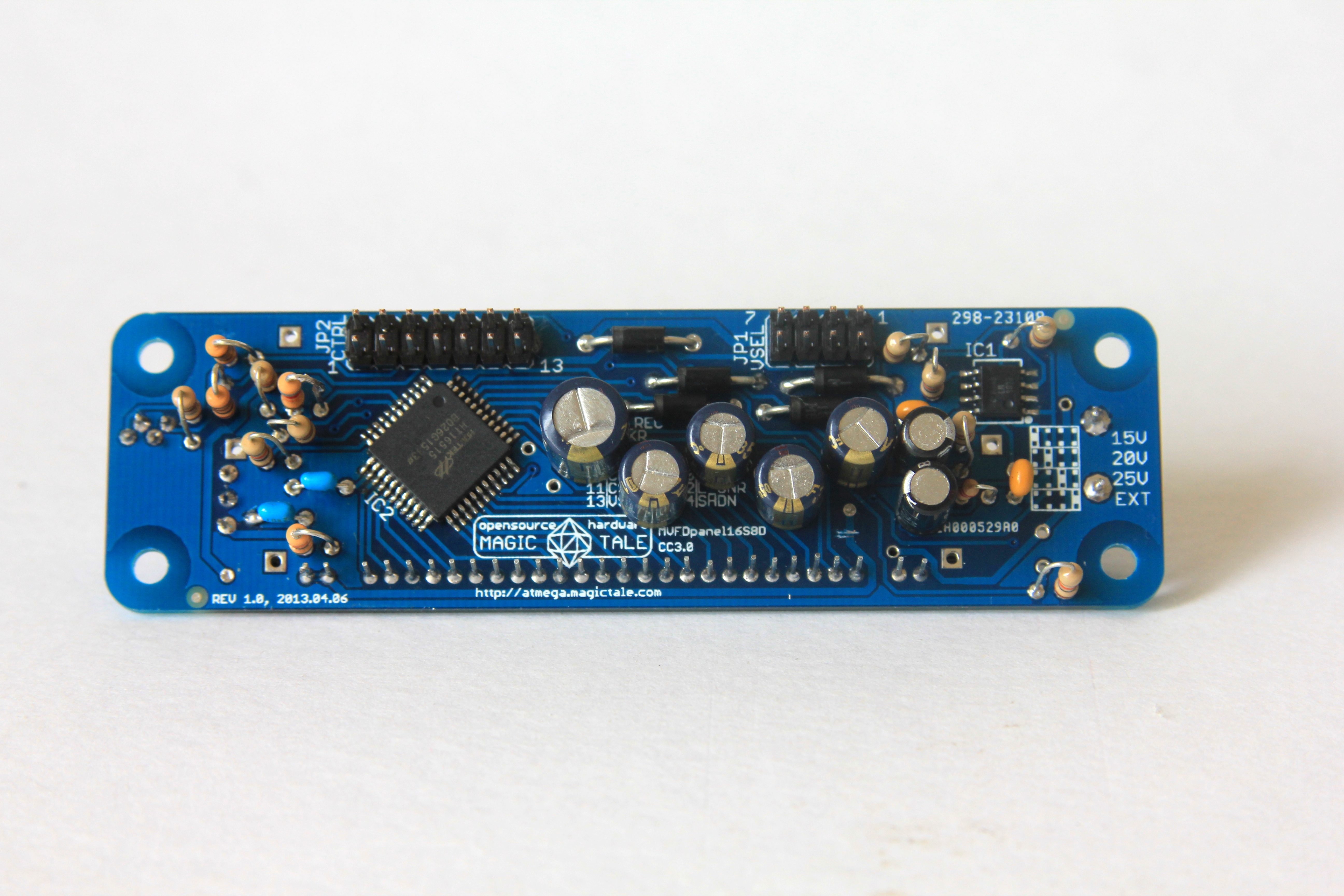
MVFD Panel 16S8D Rear View

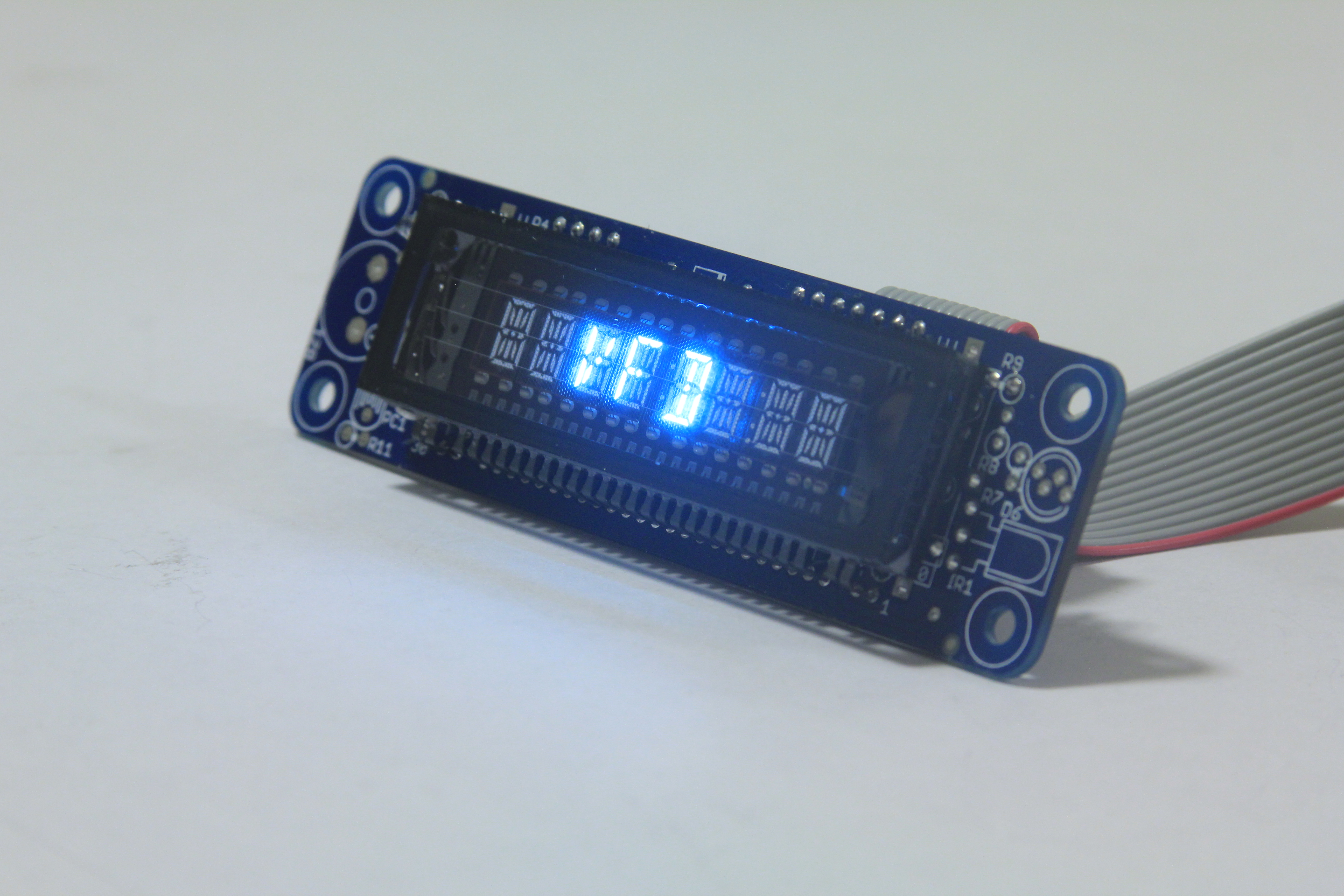
MVFD Panel 16S8D Front View In Action
MVFD Panel 16S8D ISO View In Action


Leave a Reply
You must be logged in to post a comment.